Download
1 / 10
100 likes | 224 Views
Mechanical Design Of Cooling Layout For Thermal Test of Test Module Type 0 By Faisal Bashir (NCP). Layout (Line Diagram). A Total of 12 lines, 6 each for inlet and outlet a re identified. Legend. FT. Flow transducer. Inlet/supply. Control Valve. PRV. CV. Pressure regulating valve.

E N D
Mechanical Design Of Cooling Layout For Thermal Test of Test Module Type 0 By Faisal Bashir (NCP)
Layout (Line Diagram) A Total of 12 lines, 6 each for inlet and outlet are identified
Legend FT Flow transducer Inlet/supply Control Valve PRV CV Pressure regulating valve Safety valve Schematic Representation 1/2 (Inlet/Supply) SV FT PRV HV Hand Valve SV0 CV5 CV6 CV4 CV3 CV1 CV2 Fittings/connections for valves/pipe SV6 SV1 SV4 SV3 SV2 Flexible pipe to PETSx2 Flexible pipe to DBQx2 Flexible pipe to AS1 Flexible pipe to AS2 Flexible pipe to AS3 Flexible pipe to AS4 Union for flexible pipe and inflexible tube TO TEST MODULE
Schematic Representation 2/2 (Outlet/Collection) FROM TEST MODULE Flexible pipe from Load2 Flexible pipe from DBQx2 Flexible pipe from Load1 Flexible pipe from Load3 Flexible pipe from Load4 Flexible pipe from PETSx2 Union for flexible pipe and inflexible tube HV6 SV5 Fittings/connections for valves/pipe SV7 HV2 HV1 HV4 HV5 HV3 CV7 Outlet/Collection
Components Selection All components selected are standard
Components Selection CONT…
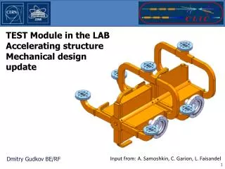
Inlet/Supply Layout (3D) Distribution Manifold Control Valve Standard Section Safety Valve Main Inlet Flow Transducer + Temp. Sensor Pressure Regulating Valve Discharge Line for Safety Valves Flexible Pipe with connection fittings
Outlet/Collection Layout (3D) Control Valve Standard Section Safety Valve Hand Valve Connection Fitting Distribution Manifold Main Outlet Flexible Pipe
Piping Support Ladder in Lab Layout Inlet/Supply Assembly Outlet/Collection Assembly Connection Fitting Ladder Support For Connection Pipes
END Thank You !