Download
1 / 3
30 likes | 177 Views
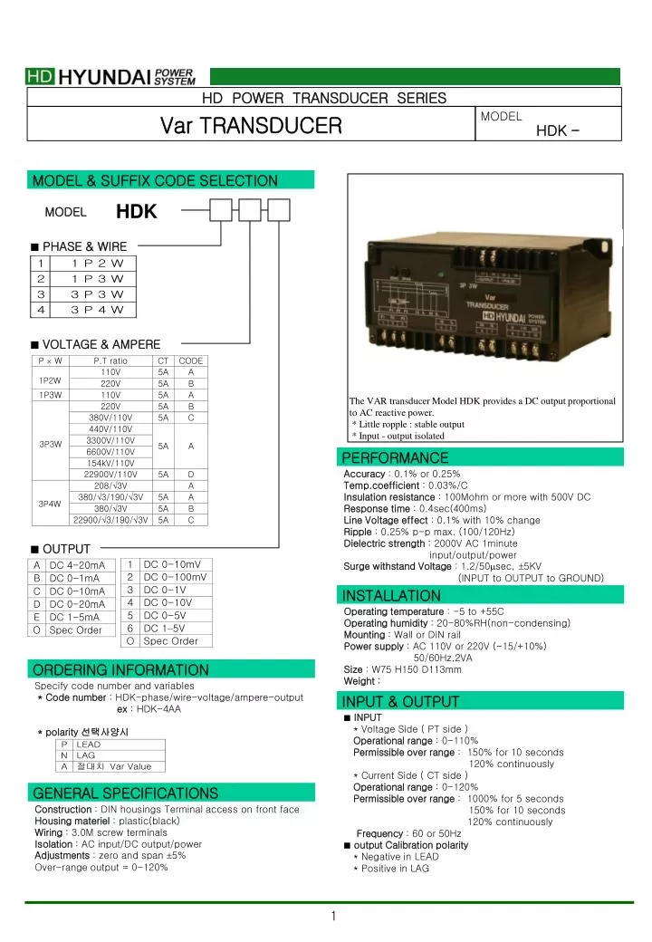
HD POWER TRANSDUCER SERIES. Var TRANSDUCER. MODEL HDK -. 1P2W. 3P3W. 3P4W. MODEL & SUFFIX CODE SELECTION. The VAR transducer Model HDK provides a DC output proportional to AC reactive power. * Little ropple : stable output * Input - output isolated. HDK. MODEL. PHASE & WIRE.

E N D
HD POWER TRANSDUCER SERIES Var TRANSDUCER MODEL HDK - 1P2W 3P3W 3P4W MODEL & SUFFIX CODE SELECTION The VAR transducer Model HDK provides a DC output proportional to AC reactive power. * Little ropple : stable output * Input - output isolated HDK MODEL • PHASE & WIRE • VOLTAGE & AMPERE PERFORMANCE Accuracy : 0.1% or 0.25% Temp.coefficient : 0.03%/C Insulation resistance : 100Mohm or more with 500V DC Response time : 0.4sec(400ms) Line Voltage effect : 0.1% with 10% change Ripple : 0.25% p-p max. (100/120Hz) Dielectric strength : 2000V AC 1minute input/output/power Surge withstand Voltage : 1.2/50sec, 5KV (INPUT to OUTPUT to GROUND) • OUTPUT INSTALLATION Operating temperature : -5 to +55C Operating humidity : 20-80%RH(non-condensing) Mounting : Wall or DIN rail Power supply : AC 110V or 220V (-15/+10%) 50/60Hz,2VA Size : W75 H150 D113mm Weight : ORDERING INFORMATION Specify code number and variables * Code number : HDK-phase/wire-voltage/ampere-output ex : HDK-4AA * polarity 선택사양시 INPUT & OUTPUT • INPUT * Voltage Side ( PT side ) Operational range : 0-110% Permissible over range : 150% for 10 seconds 120% continuously * Current Side ( CT side ) Operational range : 0-120% Permissible over range : 1000% for 5 seconds 150% for 10 seconds 120% continuously Frequency : 60 or 50Hz • output Calibration polarity * Negative in LEAD * Positive in LAG GENERAL SPECIFICATIONS Construction : DIN housings Terminal access on front face Housing materiel : plastic(black) Wiring : 3.0M screw terminals Isolation : AC input/DC output/power Adjustments : zero and span 5% Over-range output = 0-120%
OUTPUT LOAD RESISTANCE IMPEDANCE 4-20mA 0-600 Ω 5M Ω or more 0-20mA 0-600 Ω 0-16mA 0-750 Ω 0-10mA 0-1200 Ω 0-1mA 0-12k Ω OUTPUT LOAD RESISTANCE IMPEDANCE 0-5mA 0-2400 Ω 0-10mV 10 Ω 10k Ω or more 0-100mV 100 Ω 100k Ω or more 0-1V 1 Ω or less 1k Ω or more 0-10V 10k Ω or more 0-5V 1-5V 5k Ω or more * for other ranges within 0-12V, use equation R = E/I where : R = load resistance (Ω) E = full-scale output (V) I = 1 mA • INPUT RANGE 1-PHASE/2-WIRE 1-PHASE/3-WIRE 3-PHASE/3-WIRE 3-PHASE/4-WIRE HOW TO DETERMINE Var RANGE Measuring Var Value(Var) = PT ratio CT ratio STANDARD RANGE[Var] Check that the required calibration range is within the available range in the table, specify this range when ordering. [example] 3-phase/3-wire , PT 3300/110V, CT 250/5A Measuring Var Value = 3300/110 250/5 500Var = 75KVar • OUTPUT DC Current : 0-20mA DC Minimum span : 1mA zero bias : max. 1.5 Times of span LOAD resistance DC Voltage : 0-12V DC Minimum span : 5mV zero bias : max. 1.5 Times of span
CONNECTION DIAGRAM DEMENSION & INSTRUCTIONS