Download
1 / 20
210 likes | 450 Views
The ALMA Telescope Control System. Allen Farris Ralph Marson Jeff Kern National Radio Astronomy Observatory. The ALMA Project (Atacama Large Millimeter Array). 64 ( 50 funded ) x 12m antennas , 30-950 GHz Array configurations:150 m-14 Km Near S. Pedro de Atacama, Chile at 5000 m

E N D
The ALMA Telescope Control System Allen Farris Ralph Marson Jeff Kern National Radio Astronomy Observatory The ALMA Telescope Control System
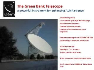
The ALMA Project(Atacama Large Millimeter Array) • 64 (50 funded) x 12m antennas , 30-950 GHz • Array configurations:150 m-14 Km • Near S. Pedro de Atacama, Chile at 5000 m • EU and North America as equal partners • Japan will add Compact Array: 12 x 7m + 4 x 12m antennas and extra correlator, receivers The ALMA Telescope Control System
ALMA The ALMA Telescope Control System
ALMA Computer Network • In addition to non-real-time computers, ALMA will have over 70 computers that operate in real-time that may be separated by distances of 14 Km. • ALMA makes heavy use of CORBA for distributed processing. • Many parts of the system are in Java, but critical real-time code is in C++ or C. Python is also used as a high-level scripting language. The ALMA Telescope Control System
Physical Architecture The ALMA Telescope Control System
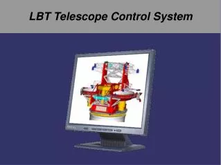
An Antenna The ALMA Telescope Control System
Central Devices The ALMA Telescope Control System
Control Computer The ALMA Telescope Control System
The Software Context The ALMA Telescope Control System
Component/Container Model • The component/container model in ALMA Common Software (ACS) is the major feature that allows us to manage and access objects via CORBA. • All major software modules (a collection of classes) are components that run under the control of a container. • The ACS Manager controls the deployment of components throughout the network. The ALMA Telescope Control System
Containers • Language specific: C++, Java or Python. • Manage the lifecycle of components. When a client requests the services of a component the manager tells the container to load it (if it isn’t already loaded) and the container gives the client access to it. • Provide services to components, such as logging, error handling, and access to other components. The ALMA Telescope Control System
Components • A component is a CORBA object with an IDL interface that is available to clients. • Crafting a component is fairly easy: An “ordinary” class (in Java for example) is required to: • Implement certain ACS lifecycle methods required of all components and, • Implement the public IDL methods that it makes available to external clients. The ALMA Telescope Control System
Use of Components and Containers in Control • The Control system uses all three types of containers: Java, C++, and Python. • Every antenna in ALMA has its own computer (ABM) and its own container on that computer. • Each hardware device on the antenna is represented as a component in that antenna’s container. • In addition, the antenna itself is a component that is commanded and controlled by the Master Component that controls the entire ALMA array. The ALMA Telescope Control System
Properties of Components • Components may define properties. • These may be hardware device monitor points such as the value of a voltage, temperature, frequency setting, or a state variable (busy, idle, error, etc.). • ACS provides facilities for monitoring properties based on time intervals or other logical criteria (such as when value changes by a certain amount). • Values of properties are gathered and stored permanently in the archive. This is a very important part of the Control system. The ALMA Telescope Control System
A Run-Time View of Control The ALMA Telescope Control System
Time Keeping • Computers are divided into real-time and non-real-time. Non-real-time computers use Network Time Protocol (NTP). NTP is too inaccurate for real-time computers. • There is only one master clock in the system. • All real-time computers have dedicated connections to a central computer (ARTM) that functions as a time server based on this one master clock. The ALMA Telescope Control System
Time Keeping • The Master Clock design uses a maser connected to a GPS receiver. • The Master Clock generates timing signals at 2GHz, 150MHz and 20.83Hz (a 48ms pulse). • The 48ms pulse, known as the timing event (TE), is distributed to all real-time computers where it generates an interrupt. The real-time computers need to respond in this 48ms window. The ALMA Telescope Control System
Synchronization • The first 24 milliseconds of the TE window is used to execute real-time commands. • Precisely timed events are queued to be executed on a TE boundary. Events across the array can be synchronized to an accuracy of ½ nanosecond (because the 48ms and 2GHz timing signals are generated from the same source). • If “external” time is associated with an event, this can be done to an accuracy of 40 nanoseconds. The ALMA Telescope Control System
External Time and Errors • On the ARTM the base time is derived from the GPS. • Time is maintained by the real-time computers by counting TEs. (All time is Atomic Time.) • Other real-time computers communicate with the ARTM to get the base time. The transaction (“getTimeAtNextTE”) that distributes the base time to all the real time computers is timed and retried if it takes too long. • The getTimeAtNextTE call comes from the distributed real-time computer and is sent to the ARTM. The ALMA Telescope Control System
Current Status • 2 prototype antennas located at the VLA site in Socorro, New Mexico • First production antenna delivered in Chile in 15 months • Construction phase 2003-2011 • Early Science foreseen for 2009 The ALMA Telescope Control System