Download
1 / 56
940 likes | 1.82k Views
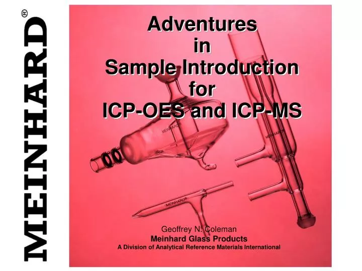
Adventures in Sample Introduction for ICP-OES and ICP-MS. Geoffrey N. Coleman Meinhard Glass Products A Division of Analytical Reference Materials International. Sample Introduction Components. ICP Torches Spray Chambers Nebulizers Conventional High Efficiency Direct injection

E N D
Adventures in Sample Introduction for ICP-OES and ICP-MS Geoffrey N. Coleman Meinhard Glass Products A Division of Analytical Reference Materials International
Sample Introduction Components • ICP Torches • Spray Chambers • Nebulizers • Conventional • High Efficiency • Direct injection • Accessories
Overview • Brief review • Components • Torches • Spray chambers • Nebulizers • What’s new....
References Richard F. Browner, Georgia Institute of Technology Anders G.T. Gustavsson, Swedish Institute of Technology Jean-Michel Mermet, Universite Claude Bernard-Lyon, France Akbar Montaser, George Washington University John W. Olesik, Ohio State University Barry L. Sharp, Macauley Land Use Institute, Scotland “Pneumatic Nebulizers and Spray Chambers for Inductively Coupled Plasma Spectroscopy”, Journal of Analytical Atomic Spectrometry, 1988, 3, 613 – 652 (Part 1); 939 – 963 (Part 2).
Processes Starting with a “homogeneous” solution sample.... • Nebulization • Desolvation • Dissociation • Excitation All require energy and time. There is a “domino” effect.
Interferences • Nebulization • Desolvation • Dissociation • Excitation Probably 85% of significant interferences occur at nebulization, due to changes in surface tension, density, and viscosity. These are multiplicative interferences.
1.5 0.45 0.5 3 ù h é ù é 10 Q é ù 585 s l d + 597 = ê ú ê ú ê ú 3,2 ë û V r Q 0.5 ë û ( sr ) ë û g Mean Droplet Size NUKIYAMA AND TANASAWA EQUATION d3,2 = Sauter mean diameter - (m) V = Velocity difference of gas-liquid - (m/s) = Surface tension - (dyn/cm) = Liquid density - (g/cm3) = Liquid viscosity - (Poise or dyn·s/cm2) Ql = Volume flowrate, liquid - (cm3/s) Qg = Volume flowrate, gas - (cm3/s) S. Nukiyama and Y. Tanasawa, Trans. Soc. Mech. Eng., Tokyo, 1938-40, Vol. 4 – 6, Reports 1 – 6.
Rule-of-Thumb When the Total Dissolved Solids exceeds about 1000 ppm, changes in surface tension, density, and viscosity begin to affect the droplet size distribution and, thus, the slope of the analytical calibration curve.
Interferences Control by: • Matrix Removal – usually not practical • Swamping – risk of contamination • Matrix Matching – probably most useful • Internal Standard – line selection • Method of Standard Additions – most tedious and time-consuming
Single Droplet Studies Desolvation begins Evaporation from surface Droplet diameter diminishes Crust forms as solvent evaporates Internal pressure builds Droplet explodes Escaping water vapor cools immediate surroundings Particles dehydrate Particles evaporate
Implications • Large Surface Area/Volume • Small Droplets • Faster desolvation and vaporization • Narrow Size Distribution • Consistent desolvation and vaporization • Well-defined excitation/observation zones • Virtually no signal comes from droplets larger than 8 - 10 m • Most signal comes from < 3 m.
ICP Plasma Torches • Tg 6000 – 9000 K • Skin Effect • Electric • Magnetic • Pressure/Temperature • Injection Velocity 3 – 5 m/sec to overcome skin effects Injector diameter 1.0 – 2.4 mm i.d. Carrier at 0.7 – 1.0 L/min • Residence Time • Highly Volatile Solvents • Chemical Interferences • Viewing Zone
ICP Plasma Torches End-on Viewing • Must remove “tail flame” • Ground state atoms • Molecular species • Larger injector diameters – longer residence time • Significant chemical interferences • Significant sensitivity improvement – up to 10x
ICP Plasma Torches • Outside: 16 – 18 mm • Inner – Outer Gap: 0.5 – 1.0 mm • Injector: 1.0 – 4.0 mm • 1.0 mm for volatile solvents • 2.0 mm general purpose radial torch • 2.4 mm general purpose axial torch • Demountable Injectors • Ceramic (alumina) or sapphire for HF • Flexibility • Complexity • Cost
ICP Spray Chambers Aerosol Conditioning • Remove droplets larger than 20 um • Gravitational settling • Inertial impaction • Evaporation • Recombination • Reduce aerosol concentration • Modify aerosol phase equilibria • Modify aerosol charge equilibria • Reduce turbulence of nebulization
ICP Spray Chambers Particle Motion in a Spray Chamber
ICP Spray Chambers Scott Double-Pass • Large volume (> 100 mL) • Large surface area • Phase equilibria • Stagnant areas • Long stabilization time • Long washout • Drainage
ICP Spray Chambers Cyclonic with Baffle • Moderate volume: 50 mL • Moderate surface area • Entire volume swept by carrier flow • Fast equilibration • Fast washout • Sensitivity enhanced by 1.2 – 1.5x • Now most common type
ICP Spray Chambers • Desolvation begins in the spray chamber • Extent affects droplet size • Affects amount transported to the plasma • Maintain constant temperature • Liquid on the walls must equilibrate with vapor • Minimize surface area • Drain away excess quickly
ICP Spray Chambers • Speciation begins in the spray chamber • Volatile species in gas phase are more efficiently transported than droplets • Nebulization does not control the rate of sample introduction • Cool spray chamber (especially for organic solvents) • Minimize surface area
Pneumatic Self-aspirating Concentric Cross-flow Non-aspirating Babington V-groove GEM Cone MiraMist Grid Fritted Other Ultrasonic nebulizer Thermospray Spark ablation Laser ablation Specialty HEN, MCN, MicroMist DIHEN, DIN Nebulizers
1.5 0.45 0.5 3 ù h é ù é 10 Q é ù 585 s l d + 597 = ê ú ê ú ê ú 3,2 ë û V r Q 0.5 ë û ( sr ) ë û g Mean Droplet Size NUKIYAMA AND TANASAWA EQUATION d3,2 = Sauter mean diameter - (m) V = Velocity difference of gas-liquid - (m/s) = Surface tension - (dyn/cm) = Liquid density - (g/cm3) = Liquid viscosity - (Poise or dyn·s/cm2) Ql = Volume flowrate, liquid - (cm3/s) Qg = Volume flowrate, gas - (cm3/s) S. Nukiyama and Y. Tanasawa, Trans. Soc. Mech. Eng., Tokyo, 1938-40, Vol. 4 – 6, Reports 1 – 6.
Self-Aspirating Nebulizers • Concentric • Gouy design (1897) • Efficiency approaching 3% • Glass • Quartz • Teflon • Cross-flow • Efficiency approaching 2.5% • Glass • Sapphire
Self-Aspirating Nebulizers Glass Concentric
Self-Aspirating Nebulizers Glass Concentric
Self-Aspirating Nebulizers Cross-flow
Non-aspirating Nebulizers • Original Babington Design (1973) • Very inefficient • Could nebulize “anything” • V-groove (Suddendorf, 1978) • Much improved efficiency, > 1% • Best choice for analysis of slurries • Best choice for analysis of used oils • Grid (Hildebrand, 1986) • Efficiency approaching 4.5% • Very difficult to maintain
Non-aspirating Nebulizers V-groove (Babington)
Non-aspirating Nebulizers • GEM Cone (PerkinElmer) • Efficiency ~ 1.2% • MiraMist/Parallel-Path (Burgener) • Efficiency approaching 3 %
Non-aspirating Nebulizers • MiraMist Parallel-Path
Non-aspirating Nebulizers Ultrasonic Nebulizer • Efficiency approaches 30% • Sensitivity improves ~10x • Droplet size < 5 m • Potentially heavy solvent load • Desolvation essential Membrane separator available • Desolvation interferences occur (eg., As III vs. As IV) • Does not handle high solids well
Sample Introduction Accessories Desolvation: Apex Q from Elemental Scientific • Sensitivity improves ~10x • Uses concentric nebulizer and cyclonic spray chamber • Desolvation interferences • High solids problematic • Available in HF-resistant version
Sample Introduction Accessories Spray Chamber Cooling: PC3 from Elemental Scientific • Sensitivity improves • Reduces solvent loading • Reduces oxide interferences in ICPMS • Uses concentric nebulizer and cyclonic spray chamber • Available in HF-resistant version
Sample Introduction Accessories • Fit Kits couple liquid and gas supplies to the nebulizer • Especially useful for high pressure nebulizers
The MEINHARD®Nebulizer Type A • Lapped ends – capillary and nozzle flush • Simple, monolithic design Type C • Recessed capillary for higher TDS tolerance • Vitreous, fire-polished ends • Stronger suction Type K • Recessed capillary • Lapped ends • Lower Ar flow: 0.7 L/min
The MEINHARD®Nebulizer Intensity, 40 ppb Precision, 40 ppb BEC DL
The MEINHARD®Nebulizer Type A • Lapped ends – capillary and nozzle flush • Simple, monolithic design Type C • Recessed capillary for higher TDS tolerance • Vitreous, fire-polished ends • Stronger suction Type K • Recessed capillary • Lapped ends • Lower Ar flow: 0.7 L/min
Glass Concentric Nebulizer • Advantages • Simple, single piece desgin • All glass design, inert • Permanently aligned - self aligning • Easy to use • Disadvantages • Low efficiency ( ~3%) • Glass attacked by HF • High or undissolved solids may clog capillary
HF-Resistant Nebulizers • Concentric nebulizers in Teflon PFA and Polypropylene from Elemental Scientific • Typical flows: 50 – 700 L/min; 1 L/min • Integral or demountable solution tubing • Efficiency: 2 – 3% MicroFLOW PFA PolyPro
HF-Resistant Kits Complete Kits include: • Demountable Torch • Pt or Sapphire Injector • Adapter • Teflon PFA Spray Chamber • Teflon PFA or Polypropylene Nebulizer
1.5 0.45 0.5 3 ù h é ù é 10 Q é ù 585 s l d + 597 = ê ú ê ú ê ú 3,2 ë û V r Q 0.5 ë û ( sr ) ë û g Mean Droplet Size NUKIYAMA AND TANASAWA EQUATION d3,2 = Sauter mean diameter - (m) V = Velocity difference of gas-liquid - (m/s) Ql = Volume flowrate, liquid - (cm3/s) Qg = Volume flowrate, gas - (cm3/s) • Adjust annulus to increase V, but maintain Qg • Adjust capillary to decrease Ql
High Efficiency Nebulizer Type A HEN
High Efficiency Nebulizer PN: TR-30-A3 MicroConcentric Nebulizer (Cetac) MicroMist (Glass Expansion)
High Efficiency Nebulizer • The HEN normally aspirates 30 – 300 L/min • Design gas flow is 1 L/min of argon • Normal operating pressure is 170 psi, 150 and 90 psi versions are available.
High Efficiency Nebulizer • Under normal operating conditions, a HEN exhibits a D3,2 of 1.2 – 1.5 m • “Starved” TR-30-A3 exhibits D3,2 of 3.2 – 4.2 m • Normal operating conditions for a TR-30-A3 yield a mean droplet size of about 15 m