Download

1 / 50
500 likes | 795 Views
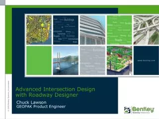
Roadway Designer Overview. Derricke Gray GEOPAK Product Manager. Corridor Modeling. Corridor Modeling Application Applications > Road > 3D Tools > Corridor Modeling. Corridor Modeling. Create Template. Corridor Modeling. Roadway Designer. Roadway Designer.

E N D
Roadway Designer Overview Derricke Gray GEOPAK Product Manager
Corridor Modeling Corridor Modeling Application Applications > Road > 3D Tools > Corridor Modeling
Corridor Modeling Create Template
Corridor Modeling Roadway Designer
Roadway Designer • With the exception of the Vertical Gore tool, the Roadway Designer application is exactly the same in both InRoads and GEOPAK. • The Vertical Gore tool is scheduled to be added to the GEOPAK version in V8i (SELECTseries 2).
Roadway Designer • At its most basic, the Roadway Designer workflow is very simple. Create a Corridor Apply a template
Manage Corridors • The creation of corridors is handled via the Manage Corridors tool. A corridor is created using a specified Horizontal and Vertical alignment.
Manage Corridors • You may have multiple corridors on a given project.
Managing Corridors • However, keep in mind that the Manage Corridors tool provides the means to evaluate several design alternatives as well.
Managing Corridors • Using the Copy command, a user can copy a complete design to an alternate Corridor name within the same design IRD file.
Managing Corridors • Likewise using the Copy From command, a user can copy a complete design to an alternate Corridor name from within another design IRD file.
Managing Corridors • By copying a design corridor to a different alternate name a user can easily evaluate design changes such as: • Profile alternates • Design speed changes • Super elevation changes • Etc.
Template Drops • Once a corridor is created, templates can be dropped at specified intervals along the corridor.
Template Drops • Once a corridor is created, templates can be dropped at specified intervals along the corridor.
Critical Sections • The Options dialog also provides the ability to create critical sections at the following locations: Horizontal Control Points (PC, PT, etc.) Vertical Control Points (VPI, VPC, etc.) External Control Points
Key Stations • The Key Stations dialog also allows you to create critical sections at any location that you wish.
Display References • Display References can be used to display selected alignments in both the plan and cross section views of Roadway Designer.
Overriding the Template • As good as a template may be, there will always be times on project where you need to ‘override’ the original template settings. For example, the template may call for a 6:1 fill but for R/W reasons you may want to use a 3:1 slope. There are several tools available in Roadway Designer that give the user control over the behavior of a template.
End Condition Exceptions • End Condition Exceptions are used to modify the behavior of an end condition solution without requiring the use of additional template drops.
Point Controls • Point controls are used to modify the behavior of points in a template. These controls take precedence over existing constraints on the point.
Parametric Constraints • These user defined values are used to override template constraint values for specified station ranges.
Target Aliasing • Target aliases can be used so that one corridor can target the solution of another corridor.
Template Transitions • Point naming consistency between templates allows transitions to complete automatically.
Template Transitions • If the transition is not handled automatically, then the transitioning between different templates can be handled in two different ways: Edit Transition dialog Template Stationing
Superelevation • Superelevation in Roadway Designer can be handled using two different methods: Superelevation Wizard Import GEOPAK Shape Input File
Shoulder Rollover • Similarly, shoulder rollovers can be handled in multiple ways as well.
Create Surface • Use this dialog to create a surface or surfaces from the roadway design. You can create a unified or merged surface out of all the corridors in the design, or create a separate surface for each corridor.
Secondary Alignments • Secondary alignments are used to modify the direction of cross section processing. By default, the cross section is created radial to the main alignment/feature. If a secondary alignment exists, then that portion of the cross section which lies outside the secondary alignment will be radial to the secondary alignment instead of the main alignment.
.IRD • Finally, your Roadway Designer session can be saved to an .IRD file. This can then be re-loaded at any time or even sent to another user.
Roadway Designer Overview Derricke Gray GEOPAK Product Manager