Download
1 / 16
200 likes | 418 Views
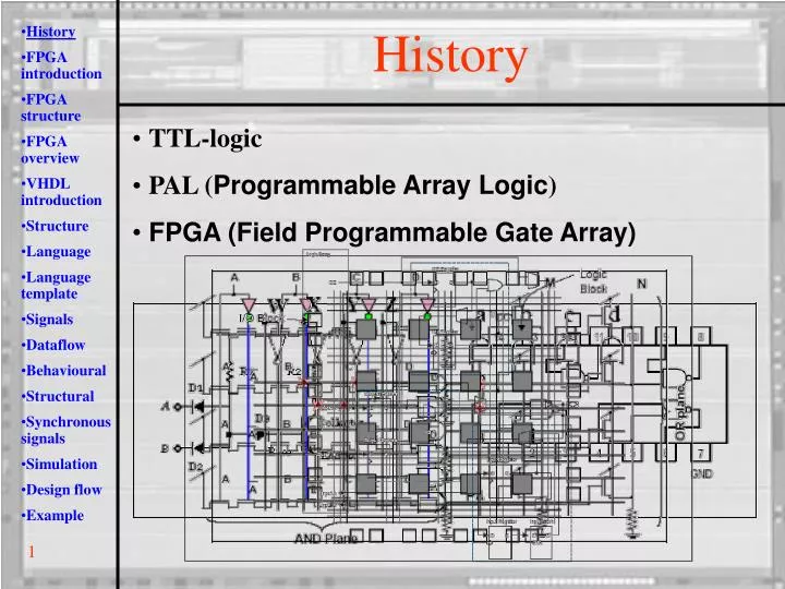
History FPGA introduction FPGA structure FPGA overview VHDL introduction Structure Language Language template Signals Dataflow Behavioural Structural Synchronous signals Simulation Design flow Example. History. TTL-logic PAL ( Programmable Array Logic )

E N D
History • FPGA introduction • FPGA structure • FPGA overview • VHDL introduction • Structure • Language • Language template • Signals • Dataflow • Behavioural • Structural • Synchronous signals • Simulation • Design flow • Example History • TTL-logic • PAL (Programmable Array Logic) • FPGA (Field Programmable Gate Array) 1
History • FPGA introduction • FPGA structure • FPGA overview • VHDL introduction • Structure • Language • Language template • Signals • Dataflow • Behavioural • Structural • Synchronous signals • Simulation • Design flow • Example FPGA Introduction • Logical element / slice • Programmable interconnections • RAM, DSP, PLL, IO, … 2
History • FPGA introduction • FPGA structure • FPGA overview • VHDL introduction • Structure • Language • Language template • Signals • Dataflow • Behavioural • Structural • Synchronous signals • Simulation • Design flow • Example FPGA Structure • Look-up table [ F’=f(F1,F2,F3,F4) ] • Flip-flop • Multiplexer 3
LC’s Various Virtex family Spartan family Various Stratix family Cyclone family RAM bits I/O • History • FPGA introduction • FPGA structure • FPGA overview • VHDL introduction • Structure • Language • Language template • Signals • Dataflow • Behavioural • Structural • Synchronous signals • Simulation • Design flow • Example FPGA Overview 4
History • FPGA introduction • FPGA structure • FPGA overview • VHDL introduction • Structure • Language • Language template • Signals • Dataflow • Behavioural • Structural • Synchronous signals • Simulation • Design flow • Example VHDL Introduction • VHDL (VHSIC Hardware Description Language) • VHSIC (Very High Speed Integrated Circuit) • Original: Language for description, simulation and documentation of digital systems • Now: Language for description, simulation, documentation and syntheses of digital systems • First developments around 1970 • First standardization in 1987 by IEEE (IEEE 1076-1987) • Later adjusted in 1993 (VHDL-93) • Again adjusted in 2001 (VHDL-2001) • Other languages (Verilog, Abel, ..) are available 5
History • FPGA introduction • FPGA structure • FPGA overview • VHDL introduction • Structure • Language • Language template • Signals • Dataflow • Behavioural • Structural • Synchronous signals • Simulation • Design flow • Example Structure • Component (inputs, outputs, behaviour) • Entity, architecture, signals 6
History • FPGA introduction • FPGA structure • FPGA overview • VHDL introduction • Structure • Language • Language template • Signals • Dataflow • Behavioural • Structural • Synchronous signals • Simulation • Design flow • Example Language XOR function entity XORport is port ( A,B: in BIT; C: out BIT ); end XORport; architecture dataflow of XORport is begin C<=A xor B; end dataflow; 7
History • FPGA introduction • FPGA structure • FPGA overview • VHDL introduction • Structure • Language • Language template • Signals • Dataflow • Behavioural • Structural • Synchronous signals • Simulation • Design flow • Example Language Template architecture architecture-name of entity-name is variable declarations signal declarations constant declarations function definitions component declarations begin concurrent-statement; … concurrent-statement; end architecture-name; entity entity-name is port ( signal-names : mode signal-type; … signal-names : mode signal-type ); end entity-name; 8
History • FPGA introduction • FPGA structure • FPGA overview • VHDL introduction • Structure • Language • Language template • Signals • Dataflow • Behavioural • Structural • Synchronous signals • Simulation • Design flow • Example Signals • Signal-modes: • in • out • buffer • inout • Signal-types: • bit (‘1’ or ‘0’) • bit_vector (combination of bits) • boolean (‘true’ or ‘false’) • integer (-231+1 to +231-1) • real • user-defined types (defined by libraries) • std_logic • std_logic_vector • Problems with bit signal-types: • Unknown values • Don’t care • Pull-up or pull-down • Tri-state • std_logic type: • ‘U’ --Not initialized • ‘X’ --Forcing Unknown • ‘0’ --Forcing 0 • ‘1’ --Forcing 1 • ‘Z’ --High Impedance • ‘W’ --Weak Unknown • ‘L’ --Weak 0 • ‘H’ --Weak 1 • ‘-’ --Don’t care • Signal • Physical value • Line or register in design • Has history of values • Can be observed in simulation • Variable • Temporally value • Only defined in process, block, procedure, function • Used to make design more readable • Can’t be observed in simulation • Constant • Used in generic programming • Used to make design more readable • Can’t be observed in simulation 9
Q<=R nor nQ nQ<=S nor Q • History • FPGA introduction • FPGA structure • FPGA overview • VHDL introduction • Structure • Language • Language template • Signals • Dataflow • Behavioural • Structural • Synchronous signals • Simulation • Design flow • Example Dataflow • C<=A xor B; • Defines direct relation between output and input • Sequence not important (parallelism) • Asynchronous • Difficult for complex functions • Difficult to understand • Q<=R nor nQ • nQ<=S nor Q • start : R='0', S='0', Q='1', nQ='0‘ • step 1: R='1', S='0', Q='1', nQ='0‘ (Assert R) • step 2: R='1', S='0', Q='0', nQ='0‘ (Q changes) • step 3: R='1', S='0', Q='0', nQ='1‘ (nQ changes) • step 4: R=‘1', S='0', Q='0', nQ='1‘ (no changes => stop) 10
for variable/signal-name in start-value to stop-value loop action; end loop; if (condition) then action1; elsif (condition) then action2; ... else action3; end if; case (signal-name) is when condition => action1; ... when others => action2; end case; • History • FPGA introduction • FPGA structure • FPGA overview • VHDL introduction • Structure • Language • Language template • Signals • Dataflow • Behavioural • Structural • Synchronous signals • Simulation • Design flow • Example Behavioural • Sequence important • Asynchronous • Divides complex functions in manageable parts • Easier to understand process(signal-names) begin -- sequential code: e.g.: if (condition) then action1; else action2; end if; end process; 11
History • FPGA introduction • FPGA structure • FPGA overview • VHDL introduction • Structure • Language • Language template • Signals • Dataflow • Behavioural • Structural • Synchronous signals • Simulation • Design flow • Example Structural --component declarations component entity-name port ( signal-names : mode signal-type ); end component; … --signals to connect blocks signal-names : mode signal-type; begin component-name : component port map ( signal-mapping ); … • Divide problems into sub-problems • Connecting blocks • Reuse 12
History • FPGA introduction • FPGA structure • FPGA overview • VHDL introduction • Structure • Language • Language template • Signals • Dataflow • Behavioural • Structural • Synchronous signals • Simulation • Design flow • Example Synchronous Signals process(clk) begin if (clk'EVENT and clk='1') then action; end if; end process; • Rising or falling edge • No ‘else’ condition • Clock signal in process list 13
History • FPGA introduction • FPGA structure • FPGA overview • VHDL introduction • Structure • Language • Language template • Signals • Dataflow • Behavioural • Structural • Synchronous signals • Simulation • Design flow • Example Simulation • Test functionality of each block • Test interaction between blocks • Test bench written in VHDL • Assert stimuli, observe outputs • Possible to look at internal signals 14
History • FPGA introduction • FPGA structure • FPGA overview • VHDL introduction • Structure • Language • Language template • Signals • Dataflow • Behavioural • Structural • Synchronous signals • Simulation • Design flow • Example Design Flow • Create new project • Select FPGA device • Create new VHDL file • Simulation • Assign pins • Synthesis and fitting • Program device • Test new hardware 15
History • FPGA introduction • FPGA structure • FPGA overview • VHDL introduction • Structure • Language • Language template • Signals • Dataflow • Behavioural • Structural • Synchronous signals • Simulation • Design flow • Example Example • Quiz buttons (2 players, first push wins, reset) library IEEE; use IEEE.std_logic_1164.all; use ieee.std_logic_unsigned.all; entity tstbench is end tstbench; architecture test of tstbench is component QuizButton is port ( button1, button2: in std_logic; reset: in std_logic; light1, light2: out std_logic ); end component; signal clk : std_logic := '0'; signal rst : std_logic := '0'; signal testData : std_logic_vector(1 downto 0) := "00"; begin … uut: QuizButton port map ( button1=>testData(0), button2=>testData(1), reset=>rst ); end test; architecture dataflow of QuizButton is signal state1 : std_logic := '0'; signal state2 : std_logic := '0'; begin process(button1, button2, reset) begin if (button1='1' and state2='0') then state1<='1'; end if; if (button2='1' and state1='0') then state2<='1'; end if; if (reset='1') then state1<='0'; state2<='0'; end if; end process; light1<=state1; light2<=state2; end dataflow; library IEEE; use IEEE.STD_LOGIC_1164.ALL; entity QuizButton is port ( button1, button2: in std_logic; reset: in std_logic; light1, light2: out std_logic ); end QuizButton; • process(clk) • begin • clk <= not clk after 20 ns; -- 50MHz • if (clk='0') then • rst<='1'; • else • rst<='0'; • testData<="00"; • testData<=testData+1 after 10 ns; • end if; • end process; 16