Download
1 / 22
220 likes | 359 Views
CMS Beam and Radiation Monitoring. Richard Hall-Wilton (TS/LEA) On behalf of the CMS BRM Group. CMS Beam Conditions and Radiation Monitoring. CMS BRM Composed of 6 systems: BCM1 (Beam Conditions Monitor) BCM2 Pixel Luminosity Telescope (PLT) Not yet endorsed; awaiting a TDR RADMON

E N D
CMS Beam and Radiation Monitoring Richard Hall-Wilton (TS/LEA) On behalf of the CMS BRM Group
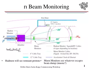
CMS Beam Conditions and Radiation Monitoring • CMS BRM • Composed of 6 systems: • BCM1 (Beam Conditions Monitor) • BCM2 • Pixel Luminosity Telescope (PLT) • Not yet endorsed; awaiting a TDR • RADMON • BSC ( Beam Scintillator Counters) • Passive Monitors • Idea is to have online monitoring of the beam and radiation conditions over time scales ranging from 25ns to 100s • This is to be backed up by monitoring based on passive monitors for long term measurements and total dose
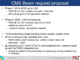
BCM requirements • Placement of BCM: • Close to beampipe • BCM1:in front of conical beampipe section, at same inner radius as Barrel Pixel Detector • BCM 2: Outside Forward hadron Calorimeter; shielded from IP, Open to showers coming from the TAS • Function • monitor particle fluxes within CMS; throw abort when necessary • Mechanical Design • BCM should be independent of the Beampipe supports • BCM should be completely independent of the pixel and HF systems • Must incorporate the possibility of a Pixel Luminosity Telescope (PLT) in the inner tracker volume • Monitoring time scales • Slow = 40 s Integration time matches the BLM monitors of the LHC. • This monitoring is done by BCM2 • Medium = 1 s integration time: • This monitoring is done by BCM1 • Leakage current monitoring inside the Tracker volume. Sensitive to 3us abort gap • Fast = MIP sensitive front end electronics that provides asynchronous monitoring on the 25ns time scale • This monitoring is done by BCM1, in an independent subsystem • Interface to the BIC • Initially Slow and Medium timescale monitoring to feed into the BIC • Fast Monitoring to be incorporated into BIC input once validated in-situ
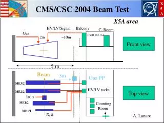
BCM1: In-situ overview BCM at insertion BCM at final position Beampipe collar FPix disks
BCM1 Design Constraints The BCM is the last object to be installed in the inner tracker volume => BCM should not interfere with anything and should provide best possible monitoring of beam halo/background in vicinity of Pixel detector z-position of BCM: z = ±1.710 to ± 1.840 m • Location implies • ~6.25ns from IP • Further away in z than the BP support collar (z= ± 1.632m) • Away from the low energy electron flux coming from the conical BP section • Possible to position BCM sensors at a radial position comparable to inner radius of pixels • Must be insertable/removable => Required some modification to Forward Pixel Service Cylinder and Beam Pipe supports BP IP
Forward Pixel service cylinder modification Old version Looking from above New version • Section of service tube that is cut away • Staggered step • Makes opening for BCM to pass No change in the way the disks are mounted
BCM Carriage The Endorsed Mechanical structure BCM Arm BCM1 Max length= 1076mm Nothing mounted on outside face of BCM carriage => Avoids interference with FPix service tube PLT telescope volume Hinge joint Opto hybrids mounted on inside face of BCM carriage arm BCM volume
BCM1_ L Leakage current measurement Sensor: polycrystalline diamond 10x10x0.4mm 7000e-/MIP No front end electronics Bias voltage: 400V (nominal) Sensor orientation set by need for ExB to avoid anomalous leakage currents Test beam in Week 25 and 26 No direct cooling BCM Unit Carbon fibre frame Modular design Compact BCM1_ F • Bunch by bunch measurement • Sensor: Single crystal diamond • 5x5x0.4mm • 18000e-/MIP • Dedicated front end electronics • AFP amplifier -> optohybrid • Bias voltage: ~100V (nominal) • Limited space for front end electronics • No direct cooling
Inside the BCM carriage • Total length of carriage is 136.5 mm • Gap between PLT and BCM=13.5 mm • Reason: Add end flange in between PLT and BCM for PLT cabling • Optohybrids for BCM ( 1 per BCM unit) • Installed in the diagonal positions of the carriage • Needed for the BCM_F (bunch by bunch) readout • Location • Minimised distance from Amp to OH • Not at larger radius as need to avoid vertical BP support wire • Standard DOH • TK tested to 10 MRad • Optimized slots for cable routing • Cables routed out bottom of carriage • Ensures cables do not exceed outer radius of Carriage ie no snaggs Cables not routed as shown here
Packaging of sensors Less than 1pA leakage current due to G10 packaging! Diamond leakage current < 10pA
Installation and Insertion • BCM1 Installation: • Starts after survey and alignment completed • Starts after BPix and FPix installed and cabled up • Starts after Beam pipe supports have been cabled up Installation and Insertion sequence • Remove lower ¼ carbon fibre wheels on one side • Position BCM carriage (in its transport/installation structure) below and to one side of the beam pipe • Dismount the to part of the BCM carriage transport structure to allow the BCM to be raised • Combined x and y direction raise BCM installation platform to bring the BCM to the correct y position, such that it is in line with the BCM rails • Move platform in z so to dock with the pixel rail plate • Partially insert the BCM carriage so that both front and back foot engage in the BCM rail of the pixel rail plate (back foot at to z=2775mm) ie top feet now engaged in rail plate • Disengage Carriage support frame that associated with the travel/installation structure • Insert BCM carriage structure using the BCM arm. Stop at final position • Remove BCM installation platform • Lock arm at z=2775mm • Cable to PP0 • Re attach lower ¼ carbon fibre wheels • Repeat steps 1 trough 12 for the other side • Test cabling • Repeat steps 1 though 14 for the other end • Hand over to Tracker integration for close up of bulkheads and go to USC area
Summary Comments • RADMON • Awaiting final agreement on locations • Concern over powering/grounding scheme • Must separate RADMON from detector • Passives • Will work with TS-LEA and will adopt passive monitors as used by Totem. ie consistency throughout CMS • BSC • Mechanical location on front of HF • Readout chain hardware fully integrated with HF • Awaiting test beam with HF in August 06 • BCM • BCM1 • Prototype readout based on Tevatron BLM cards is now ready for testing with diamonds installed in CDF • All CMS polycrystalline diamonds now delivered. Now being metalised and tested • Poly and single crystal diamonds undergoing leakage current QA in Magnetic field (CERN East Hall) • Mechanical structure endorsed at EDR; proceeding to optimise with manufacturer • Front end electronics for fast readout based on CERNs AFP chip ( rad hard 0.25um) • Full mechanical insertion test with BCM, Beam pipe and Pixels is ongoing, with no major problems • BCM2 • Full readout based on LHC_BLM system • Mechanical infrastructure based on independent mounting on CASTOR support table • Frontend electronics validated in Magnetic field equiv to CMS fringe field • Starting the LHC and CMS interface designs