Download

1 / 49
570 likes | 790 Views
EROSION TECHNOLOGY for SITES Earth Spillway Integrity Analysis Phase 3: Inputs and Equations. EROSION MEASUREMENT TRAINING: Maricopa County, AZ October 2011. SURFACE EROSION (Cover Destruction). 2. CONCENTRATED FLOW EROSION. 3 PHASE Spillway Erosion Model.

E N D
EROSION TECHNOLOGY for SITES Earth Spillway Integrity Analysis Phase 3: Inputs and Equations EROSION MEASUREMENT TRAINING: Maricopa County, AZ October 2011
SURFACE EROSION • (Cover Destruction) 2. CONCENTRATED FLOW EROSION 3 PHASE Spillway Erosion Model 3. HEADCUT ADVANCE
SPILLWAY EROSION PHASES 1. SURFACE EROSION (Cover Destruction) 2. CONCENTRATED FLOW EROSION 3. HEADCUT ADVANCE
1983 -The ESFSTG was formed 1991 - ARS & SCS established DAES Team
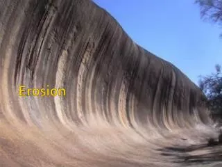
Materials observed in the field varied from weak soils that experienced extensive damage to monolithic rock that experiences little to no damage.
Material structure including block size and joints were observed to be important.
Layer thickness and orientation were also observed to play a role.
Material variation within a spillway was observed to be very important.
FIELD DATA ANALYSES Moore Data Plot - Headcut advance threshold
HEADCUT ADVANCE Phase 3 includes simultaneous deepening and upstream advance of the headcut.
DOWNCUTTING and HEADCUT ADVANCE dX/dt de/dt
SITES AUXILIARY SPILLWAY EROSION: PHASE 3 DOWNCUTTING de/dt = kd(te- tc) te = gdc0.011 (H/dc)0.582 HEADCUT ADVANCE dX/dt = C (A - Ao) A = (qH)1/3 (NEH Part 628 Dams Ch 51 Eq 51-9)
SITES AUXILIARY SPILLWAY EROSION PHASE 3 INPUT PARAMETERS DOWNCUTTING • PARTICLE DIAMETER • DRY BULK DENSITY • PERCENT CLAY or kd DETACHMENT • COEFFICIENT HEADCUT ADVANCE • Kh HEADCUT ERODIBILITY INDEX
SITES AUXILIARY SPILLWAY EROSION: PHASE 3 DOWNCUTTING de/dt = kd(te- tc) te = gdc0.011 (H/dc)0.582 HEADCUT ADVANCE dX/dt = C (A - Ao) A = (qH)1/3 (NEH Part 628 Dams Ch 51 Eq 51-9)
kd 1 Detachment Rate, er tc 0 0 Effective Stress, te SURFACE DETACHMENT . r = kd (e - c)a . r = detachment rate kd = coefficient of detachment e = effective stress c = critical tractive stress a = exponent (~ 1)
PHASE 3 Headcut Deepening • EFFECTIVE STRESS AT THE HEADCUT BASE • te= dc 0.011(H/dc)0.582 dc te H H
CRITICAL STRESS for Detachment Critical stress based on loose particle condition for all materials.
DETACHMENT RATE COEFFICIENT The detachment rate coefficient may be externally determined and entered directly in SITES or estimated by SITES from soil properties.
SITES AUXILIARY SPILLWAY EROSION: PHASE 3 DOWNCUTTING de/dt = kd(te- tc) te = gdc0.011 (H/dc)0.582 HEADCUT ADVANCE dX/dt = C (A - Ao) A = (qH)1/3 (NEH Part 628 Dams Ch 51 Eq 51-9)
HEADCUT MIGRATION dx/dt = C (A - Ao) dX/dt = rate of headcut migration, C = material dependent advance rate coefficient, A = hydraulic attack, and Ao = material-dependent threshold.
HYDRAULIC ATTACK A = (qH)1/3 q H
[ _ 189 Kh1/2exp(-3.23/ln(101Kh)) ]1/3 Kh> 0.01 AO = 0 Kh< 0.01 AND - 0.79 ln(Kh) + 3.04 Kh< 18.2 C = 0.75 Kh > 18.2 _
MATERIAL-DEPENDENT PARAMETERS AO & C are a function of Kh = headcut erodibility index
Available Tools For Estimating Kh • NEH 628, Chapter 52, Appendix B • Material Catalog on SITES CD
Headcut Erodibility Index Kh = Ms x Kb x Kd x Js • Ms = material strength number • Kb = block or particle size number • Kd = discontinuity/inter-particle bond shear strength number • Js = relative ground structure number How well they’re stuck together How easy the chunks are to rip up How big the chunks are How strong it is Kh = x x x x
Condition of the Joints • Rough or smooth • Open or closed • Gap size • material in joints Block size Kb Kd Orientation to the flow Js
Typical values for the KhFactor 0.01 Soil 0.2 Weathered Rock 0.5 Soft or Jointed Rock 10 Hard Rock
Kh = 35000 DESCRIPTION: Massive rock (ryolite) SITE: Painted Rock Dam, Arizona COMMENT: Spillway outlet, negligible erosion.
Kh = 20 DESCRIPTION: Jointed Sandstone SITE: West Fork Pint Remove 5, Arkansas COMMENT: Material remaining below surface erosion some minor detachment by flow.
Kh = 0.5 DESCRIPTION: Disintegrated shale SITE: West Fork Point Remove 5, Arkansas COMMENT: Eroding material in Gully Bank.
Kh = 0.17 DESCRIPTION: CL , stiff SITE: Rush Creek 12R, Oklahoma COMMENT: Eroding material in headcut face.
Kh = 0.01 DESCRIPTION: SM, very loose sand with little bonding SITE: Buck and Doe Run 33, Missouri COMMENT: Eroding material in spillway breach: deep deposit
Poor Quality Rock Weathered Rock Soil
Comments relative to Kh • Empirical relations based on small amount of data. • Not the only parameter important to spillway erosion. • Spillway erosion is a three phase process • Erosion is dependent on spillway slope, vegetation, material detachment erodibility, flow stress, process, etc. • Large reductions in Kh may not result in spillway breach if other factors are controlling the process. • Kh is represented in logrithmic space.
Kh issues (continued) • Technology is relatively young and will continue to require additional research and change. • classification system is based on weighted parameters. Relative importance of each element is not completely understood. • The classification system includes materials from soils to massive rock but • Difficult to determine soil structure • Original development of Kh for soil did not include soil structure. Elements were commonly assumed equal to 1 with the exception of material strength (Ms)
Parameters Impacting Phase 3 Erosion Multiple materials may be exposed in a single headcut face. Downcutting controlled by the material exposed at the base for the time step. Headcut advance controlled by the materials exposed on the headcut face.
Kh for MULTIPLE MATERIALS { } hi ln( Kh )i Kh = exp hi h1 Kh1 htotal h2 Kh2 h3 Kh3
SPILLWAY GEOLOGY ELEVATION , ft All materials in spillway to elevation of valley floor are described along a weakest path. STATION , ft
Auxiliary Spillway Profile Reaches 1 2 3 4 5 6 7 8 INLET CREST EXIT
ERODED PROFILE , ft ELEVATION The eroded profile plotted in output is a composite of all headcuts considered while evaluating breach potential. STATION , ft
SPILLWAY EROSION PHASES 1. SURFACE EROSION (Cover Destruction) 2. CONCENTRATED FLOW EROSION 3. HEADCUT ADVANCE
SURFACE EROSION • (Cover Destruction) 2. CONCENTRATED FLOW EROSION 3 PHASE Spillway Erosion Model 3. HEADCUT ADVANCE