Download
1 / 39
451 likes | 736 Views
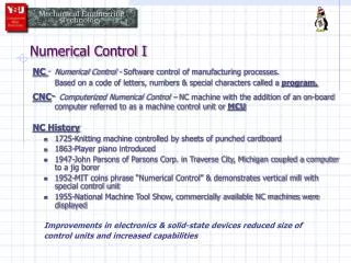
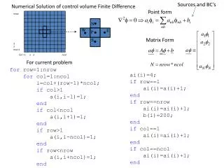
Numerical Control. It might be said that numerical control is control by numbers. Numerical control uses any of the basic machine tools. In a broad sense, numerical control converts numerical values into physical values, such as quantities and dimensions.

E N D
It might be said that numerical control is control by numbers. Numerical control uses any of the basic machine tools. In a broad sense, numerical control converts numerical values into physical values, such as quantities and dimensions.
Electronics plays an important part in numerical control. • Electronic circuits have been designed to "remember" a number. • They have been designed to turn a switch on and /or off when a particular number is reached. • This means that if a control unit can be designed to measure and "remember" numbers, the unit then has the ability to run a machine.
BASIC COMPONENTS OF AN N/C SYSTEM • 1. The control unit, which interprets the coded instructions (the tape) and directs the machine through the operations. • 2. The tape, which is punched full of holes, with each hole providing an electronic pulse. This tape holds the coded instructions. • 3. The motor, which supplies the power to move the tool or table of the machine. • 4. The electronic feedback device (transducer), which tells how much movement has taken place.
HOW NUMERICAL CONTROL WORKS • As the prepared tape passes through the tape reader head, silicon photo diodes sense light as it passes through holes in the tape. • This causes signals to be sent to the electronic control. • The number and location of the holes in each row across the tape conform to a code.
The code is interpreted by the control unit. This unit stores all information until a complete block of information is obtained. • The control then causes the motors to make the required number of steps. • During the tool cycle, the next tape block will be read and stored.
TYPES OF NUMERICAL CONTROL There are actually two forms of numerical control: • 1. Discrete positioning. This is commonly known as point-to-point. • 2. Continuous path, or contouring
PREPARATORY FUNCTION • 4 peck drill;Table moves to selected location. Peck drill cycle initiated upon arrival at location. Cycle time set by timer on console. • 5 DRILL:Table moves to selected location. Spindle moves down rapidly to preset feed point, proceeds at set feed rate to final depth and retracts rapidly. • 6 MILL:Spindle moves down rapidly to set feed point, proceeds at set feed rate to final depth and then at set mill feed rate to selected location.
7 BORE:Table moves to selected location. Spindle moves down rapidly to preset feed point, proceeds through work at set feed rate. When final depth is reached, spindle retracts from work at set feed rate to feed point and then retracts rapidly. • 8 TAP:Table moves to preset location. Spindle moves down rapidly to preset feed point. Tap feeds into work at rate determined by lead screw. When final depth is reached, the spindle reverses itself and retracts from hole to feed point. The spindle then rapidly retracts. • 9 READ Z BLOCK.This preparatory function does not initiate any motion of the table or spindle. It supplies feed point and final depth information into the machine. This depth information is then used in the next operation of the machine. This information will be read while machine is positioning for next operation.
MISCELLANEOUS FUNCTIONS • 00 PROGRAM STOP:Program is interrupted by placing the system in its manual mode of operation after completion of all commands in the block. Coolant flow and spindle feed are interrupted after the spindle has been fully retracted from the workpiece. It is necessary for the operator to push a button in order to continue with the remainder of the program. • 02 END OF program:The function signifies the completion of the workpiece. After completion of all commands in the block, the system is reset to its manual mode. Coolant flow and spindle feed are stopped after the spindle has been fully retracted from the workpiece.
06 TOOL CHANGEThis is a command to execute the change of tool(s) manually, not to include tool selection. After completion of all commands in the block, the system is placed in its manual mode of operation. Coolant flow and spindle feed are interrupted after the spindle has been fully retracted from the workpiece. • 07 COOLANT ON : This is a command to turn on flood coolant. • 08 COOLANT ON : This is a command to turn on mist coolant • 09 COOLANT OFF: This is a command to shut off all coolant. • 80 NO CHANGE IN MISCELLANEOUS FUNCTION: All miscellaneous functions remain in previously commanded operation. This applies to all miscellaneous functions with the exception of PROGRAM STOP, 02, and TOOL CHANGE, 06, which merely interrupt the sequence of automatic operations.
MEASURING BASIS FOR N/C CONTROL SYSTEMS • The Cartesian (rectangular) coordinate system is the basis for measuring N/C machine tools. • In this system, all point positions are described in terms of distances from the origin .These are called the X, Y, and Z axes.
The Cartesian Coordinate System • The Cartesian Coordinate System • A. Quadrants (4) 1. 1st quadrant (+,+) 2. 2nd quadrant (-,+) 3. 3rd quadrant (-,-) 4. 4th quadrant (+,-) • B. Origin (0,0) • C. Moog N/C Vise Location #1 Zero Offsets 1. zero offsets are always (2, -2) 2. Moog N/C is always programmed in 4th quadrant 3. Machine control does not recognize negative numbers so Y values are always programmed as positive even though in the 4th quadrant they are negative. 4. The tape coding values for the zero offset are X = 02000, Y = 02000
Components of a Typical Block • C. Components of a Typical Block 1. track numbers (1-8) 2. row numbers (1-20) 3. track values (1,2,4, and 8) 4. coded row data a. block number - rows 1-3 b. preparatory function - row 4 c. X dimension - rows 5-9 d. Y dimension - rows 10-14 e. reserved row (not used) - row 15 f. tool number - rows 16-17 g. miscellaneous function - rows 18-19 h. end of block (EOB) - row 20
Coded Numeric Data • D. Coded Numeric Data • 0 no track punched 1 track 1 punched 2 track 2 punched 3 tracks 1 & 2 punched 4 track 3 punched 5 tracks 1 & 3 punched 6 tracks 2 & 3 punched 7 tracks 1, 2, & 3 punched 8 track 4 punched 9 tracks 1 & 4 punched EOB track 8 only punched
The Fixed Decimal System • The Fixed Decimal System • A. Options 1. Full floating decimals (many N/Cs, all CNCs) 2. Fixed decimals (many N/Cs including ours) • B. Programming Implications: All X and Y coordinate information assumes the fixed decimal point is two digits from the left of a five digit dimension and a decimal point is never used. • Absolute vs Incremental Programming • A. Absolute: all dimensions are derived from their respective distances from the machine tool's origin. • B. Incremental: subsequent dimensions derive their value based on their distance from the previous dimension.
Part Dimensioning for N/C • A. Dimensioning Convention Nomenclature 1. baseline dimensioning 2. absolute dimensioning 3. datum line dimensioning 4. coordinate dimensioning • B. Eliminates "Tolerance Stack" • C. Facilitates Programming • D. Facilitates Inspection
Simple Point-To-Point Drilling Program • A. Conversion of Conventional Drawing to Coordinate Dimensioned Drawing 1. zero offsets: X = 02000, y = 02000 2. X and Y dimensions given from datums 3. sequence of operations provides for most economical tool movemen • C. Programming Sheet 1. review data in heading 2. review data for block rows (N,G,X,Y,T,M) • D. Tooling Sheet 1. data in heading 2. operation description 3. spindle feed and RPM 4. X and Y axis feed 5. tool description
Tool Presetting • A. Purposes • 1. Quick and efficient replacement of broken or dull tools • 2. close tolerances on depth dimensions (interchangeability of tools during the production cycle mandates exact uniformity of length for a given type and size of tool; this is crucial for N/C production and flexible automation (FMS/FMC))
Variance in Tool Length • 1. Fresh drills from the manufacturer come in varying lengths. • 2. Milling cutters, counterbores, spot drills, countersinks, reamers, etc., display the same characteristic • 3. Routine sharpening amplifies discrepancies in length
Setting Tool Lengths A. Procedure • Tools are loaded into their respective tool holders and clamped such that their preset length corresponds to that of the tool setting drawing within a tolerance of + or - .001" (+ or - .02mm). • This typically requires special fixtures such as vernier height gages, high-precision dial indicators . • For the purposes of standardization , the preset length for all drills destined for use on the Moog N/C will be 5.125". • Collets held cutters and very small drills will necessarily have a much shorter preset length.
N/C Exercise #2 Introduction This numerical control program is designed to systematically drill holes in a part for production. A Bridgeport N/C machine will use a drill cycle geometry code to first center drill the holes then return to the same location to drill the trough holes then once more counter boring the same holes. For this process we will use a point-to-point method. Reading further |pjti will be informed of the sequence of operations, the tools used and the references used. • Sequence of Operations Included is a tooling sheet which states the tools needed and what order they are used. For this operation a center drill will/be used to eliminate the tendency for the drill bit to walk on the parts surface. The machine continues through the all the hole locations with each tool to eliminate excessive tool changes. Once the center drill is done the tool is changed to the drill bit to/systematically drill the through holes. Once the drill has created all the through holes needed the tool is changed to the counter bore. Once the holes are counter bored the machining process is done. The tool life is optimized using calculation of speeds and feeds with numbers from The Machinery's Handbook*. These numbers are based on a forty five minute tool life for drilling operations. • Tooling Used The order of tooling has been set and should be numbered accordingly. There will be three tools used in this exercise and also three turret stop settings. The first tool listed is the number three center drill and is numbered 01. The second is the 1/8 diameter drill bit and is numbered 02. The third tool is the one quarter inch counter bore and is numbered 03. The tools have there own respective turret stop settings. No tooling material was specified nor a manufacturer so specifications for the tools would be speculation. I used tools made of high speed steel and used stock made of 4130 steel with a Brinell hardness of 200. Following is the RPM and feed rate calculations:
Cutting speed(CS) • The most important considerations for any type of machining process are cutting speed, feed and coolants. • Cutting speed(CS): Means the cutting distance in one minute. CS is normally based on surface feed per minute (SFPM). • Machine ‘s spindle speed is given in (rpm), so cutting speed should be changed to rpm. • RPM = 12 * CS/ π * d
FEED • Feed: Cutting tool should be fed into the work-piece; the bigger the drill, the slower the drill should be fed into the work-piece. • Feed is calculated in inches/rev. IPR= cpt (in/min) * # teeth IPM = RPM * IPR