Download
1 / 13
130 likes | 254 Views
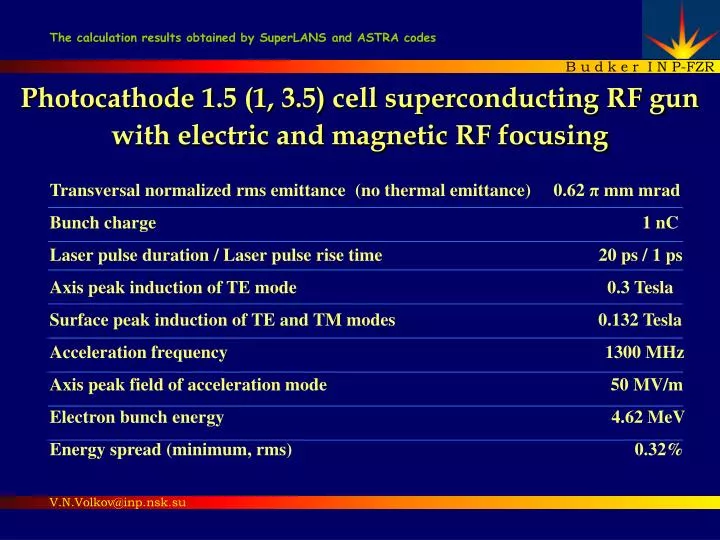
The calculation results obtained by SuperLANS and ASTRA codes. B u d k e r I N P-FZR. Photocathode 1.5 (1, 3.5) cell superconducting RF gun with electric and magnetic RF focusing. Transversal normalized rms emittance (no thermal emittance) 0.62 π mm mrad

E N D
The calculation results obtained by SuperLANS and ASTRA codes B u d k e r I N P-FZR Photocathode 1.5 (1, 3.5) cell superconducting RF gun with electric and magnetic RF focusing Transversal normalized rms emittance(no thermal emittance)0.62 πmm mrad Bunch charge1 nCLaser pulse duration /Laser pulse rise time 20 ps /1 psAxis peak induction of TE mode 0.3 Tesla Surface peak induction of TE and TM modes 0.132 TeslaAcceleration frequency 1300 MHz Axis peak field of acceleration mode 50 MV/mElectron bunch energy4.62 MeVEnergy spread (minimum, rms) 0.32% V.N.Volkov@inp.nsk.su
RF gun geometry. What are the electric and magnetic RF focusing? Electric RF focusing region Magnetic RF focusing region Cu T= 78K T=78K Scaled cathode region 1 – Heat sink 2 – Choke cell 3 – Photocathode Cu stalk 4 – Cathode cell 5 – Electric TM field pattern 6 – Magnetic TE field pattern 7 – Cavity full cell 8 – TE mode coupler (90º routed) 9 – TM mode coupler pipe
RF fields in the cavity /SLANS codThe vectors of TE and TM fields are ortogonal F=3788 MHz Peak fields F=1300 MHz
High order TE modes selectionfor low Ratio of Peak Induction (RPI) at the surface and at the axis TE011 TE021 F=2572.5 MHz F=3787.8 MHz Pipe cut off TE frequency 5226 MHz F=3899.7 MHz F=3947.2 MHz
Emittance dependence from TE field phase Set examples en – transversal normalized rms emittance eav- average emittance Ae – emittance amplitude φTE – TE mode phase o - constant phase BTE – TE mode peak induction at the axis, T R – laser spot radius at the photocathode, mm TM – launch phase(here TM=50º at maximum bunch energy) Set examples 1 2
Parameter scanning for emittance minimization/ASTRA codTE induction (BTE), laser spot size (R), launch phase (TM) Average emittance, mm Emittance amplitude, mm Optimum 0.32 0.30 0.28 0.26 0.32 0.30 0.28 0.26 φTM=46.3º BTE=0.29 T R=1.5 mm εmin=0.7mm + +0.7 + + BTE,T BTE, T Sensitivity for Den=5%: DBTE=0.03T DR=0.6 mm DTM=10º 1.0 1.25 1.5 1.75 R,mm 1.0 1.25 1.5 1.75 R, mm Launch phase scanning
Bunch time evolution Bunch cross section, mm Bunch rotates by magnetic TE field 60 cm drift Phase space, KeV/c Bunch rotation is subtracted here X, mm
Emittance compensation instances:without any RF focusing, with only electric RF focusing, with only magnetic RF focusing, with sum - electric and magnetic RF focusing [p mm mrad] - Cs2Te photocathode thermal normalized emittance [K.Floettmann studed]
1 cell superconducting RF gun (“DROSSEL”) with electric and magnetic RF focusing Optimized performances TE021 Emittance TE compensation
3.5 cell superconducting RF gun with electric and magnetic RF focusing TE021
Conclusions • Emittance compensation by the electric and magnetic RF focusing as well as a high accelerating gradient are the key factors in getting a small emittance with a large charge. • Either electric or magnetic RF focusing diminish the emittance more than twice. And together – about 6 times. • The peak induction of magnetic field on the axis is about 0.3 T. And sum of magnetic fields on cavity surface is less than the limit of 0.18 T. • The induction of peak magnetic field on cavity surface proved to be small due to vector summation of orthogonal TE and TM fields. Also because of an unoverlapping of their peak fields on the surface. • TE021 mode has a smallest ratio of magnetic peak induction on the surface to the peak induction on the axis. • The dependence of emittance from TE phase has oscillatory view. There are RF gun parameter settins at which the oscillatory amplitude becomes zero. • Transversal emittance remains small in wide range of RF gun settings.
Acknowledgments The author would like to thank Dietmar Janssen (FZR), Klauss Floettmann (DESY), Victor Petrov (BINP) for helping in the work.