Download
1 / 45
550 likes | 814 Views
Transmission Media. Semester: 131 Course: CSET 221 Computer Networking Instructor: Farhan Khan Computer Science & Engineering Technology Unit Hafr Al-Batin Community College. Outline. Guided Media Twisted-Pair Cable UTP STP Coaxial Cable Fiber-Optic Cable Multimode Single Mode

E N D
Transmission Media Semester: 131 Course: CSET 221 Computer Networking Instructor: Farhan Khan Computer Science & Engineering Technology Unit Hafr Al-Batin Community College
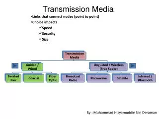
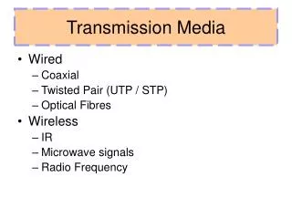
Outline • Guided Media • Twisted-Pair Cable • UTP • STP • Coaxial Cable • Fiber-Optic Cable • Multimode • Single Mode • Unguided Media • Radio Waves • Microwaves • Infrared
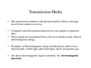
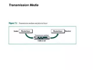
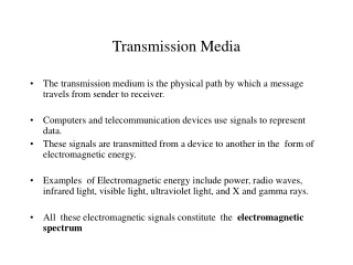
Transmission Media and Physical Layer • Computer and other telecommunication devices use signals to represent data. • Signals are transmitted from one device to another in the form of electromagnetic energy, which is propagated through transmission media.
Guided Media • Guided media are those that provide a conduit from one device to another. • Signal travelling along any of these media is directed and contained by the physical limits of the medium. • Include • twisted-pair cables • coaxial cables • fiber-optic cables
Twisted-Pair Cable • A twisted pair consists of two conductors (normally copper), each with its own plastic insulation, twisted together. • Twisting cancels out electrical noise from adjacent pairs (crosstalk) and from other noise sources.
UTP and STP Cables UTP – Unshielded Twisted Pair STP –Shielded Twisted Pair
UTP and STP Cables • STP cable has a metal foil or braided-mesh covering that encases each pair of insulated conductors. • Although metal casing improves the quality of cable by preventing the penetration of noise or crosstalk, it is bulkier and more expensive.
UTP Connectors • RJ45 (Registered Jack) is the most common UTP connector. • RJ45 is a keyed connector, meaning the connector can be inserted in only one way. RJ – Registered Jack
Coaxial Cable • Coax has a central core conductor of solid or stranded wire (usually copper) enclosed in an insulating sheath, which is, in turn, encased in an outer conductor of metal foil, braid, or a combination of the two. • The outer metallic wrapping serves both as a shield against noise and as a second conductor, which completes the circuit. • This outer conductor is also enclosed in an insulating sheath, and the whole cable is protected by a plastic cover.
Categories of Coaxial Cables • Each Radio Government (RG) number denotes a unique set of physical specifications, including the wire gauge of the inner conductor, the thickness and type of the inner insulator, the construction of the shield, and the size and type of the outer casing. RG – Radio Government
BNC Connectors • Bayonet Network Connector • aka. Bayonet Neil-Concelman • Used with coaxial cables • Three popular types are BNC connector, BNC T connector, BNC Terminator.
Optical Fiber • Fiber-Optic cable is made of glass or plastic and transmits signals in the form of light. • Based on physics of light
Optical Fiber • A glass or plastic core is surrounded by a cladding of less dense glass or plastic. • The difference in density of the two materials must be such that a beam of light moving through the core is reflected off the cladding instead of being refracted into it.
Propagation Modes • Multimode is so named because multiple beams from a light source move through the core in different paths. • Multimode step-index fiber • Density of the core remains constant from the center to the edges • Beam of light moves through this constant density in a straight line until it reaches the interface of the core and the cladding. • At the interface, there is an abrupt change to a lower density that alters the angle of the beam’s motion. The term step index refers to the suddenness of this change.
Propagation Modes • Multimode graded-index Fiber • The word index here refers to the index of refraction that is related to density. • A graded-index fiber, is one with varying densities. Density is highest at the center of the core and decreases gradually to its lowest at the edge. • Single mode Fiber • Single mode uses step-index fiber and a highly focused source of light that limits beams to a small range of angles, all close to the horizontal.
Fiber Construction • Outer jacket is made of either PVC or Teflon. • Inside the jacket are Kevlar strands to strengthen the cable. Kevlar is a strong material used in the fabrication of bulletproof vests. • Below the Kevlar is another plastic coating to cushion the fiber. The fiber is at the center of the cable, and it consists of cladding and core.
Fiber-Optic Cable Connectors • Subscriber channel (SC) connector is used in cable TV. It uses a push/pull locking system. • Straight-tip (ST) connector is used for connecting cable to networking devices. It uses a bayonet locking system and is more reliable than SC. • MT-RJ is a new connector with the same size as RJ-45
Advantages of Fiber-Optic Cable • Fiber-Optic cable has several advantages over metallic cable • Higher bandwidth, less signal attenuation, immunity to electromagnetic interference, resistance to corrosive materials, light weight, more immune to tapping. • Disadvantages: Installation/maintenance [need expertise], Unidirectional [propagation of light is unidirectional], Cost.
Unguided Media: Wireless • Transport electromagnetic waves without using a physical conductor • Radio Waves • Microwaves • Infrared • Often referred to as wireless communication
Electromagnetic Spectrum • Figure shows the part of the electromagnetic spectrum, ranging from 3 kHz to 900 THz, used for wireless communication.
Ground Propagation • In ground propagation, radio waves travel through the lowest portion of the atmosphere, along the earth. • These low-frequency signals emanate in all directions from the transmitting antenna and follow the curvature of the planet. • Distance depends on the amount of power in the signal: The greater the power, the greater the distance.
Sky Propagation • In sky propagation, higher-frequency radio waves radiate upward into the ionosphere (the layer of atmosphere where particles exist as ions) where they are reflected back to earth. • This type of transmission allows for greater distances with lower output power.
Line-of-Sight Propagation • In line-of-sight propagation, very high-frequency signals are transmitted in straight lines directly from antenna to antenna. • Antennas must be directional, facing each other, and either tall enough or close enough together not to be affected by the curvature of the earth.
Bands • The section of the electromagnetic spectrum defined as radio waves and microwaves is divided into eight ranges, called bands, each regulated by government authorities. • These bands are rated from very low frequency (VLF) to extremely high frequency (EHF).
Radio Waves • Radio waves are electromagnetic waves ranging in frequencies between 3 KHz and 1 GHz and those between 1 GHz and 300 GHz are called Microwaves. • Radio waves • Are Omnidirectional; Propagate to long distances • Can penetrate walls so we cannot isolate a communication to just inside or outside a building.
Radio Waves • Radio waves are used for multicast communications, such as radio and television, and paging systems. • They can penetrate through walls. • Highly regulated. • Use omnidirectional antennas
Microwaves • Microwaves are used for unicast communication such as cellular telephones, satellite networks,and wireless LANs. • Higher frequency ranges cannot penetrate walls. • Use unidirectional antennas - point to point line of sight communications.
Infrared • Infrared are electromagnetic waves ranging in frequencies between 300 GHz and 400 THz Infrared signals can be used for short-range communication in a closed area using line-of-sight propagation.
Summary • Guided Media • Twisted-Pair Cable • Coaxial Cable • Fiber-Optic Cable • Unguided Media • Radio Waves • Microwaves • Infrared