Download
1 / 16
160 likes | 280 Views
VGD-33 single unit upgrade to parallel system. All single units must work properly Installation of the external cables and power cords: all should be connected firmly. VGD-40K3-DTT-0010N single unit PCB setting. PCB P430 : CN26 pin 1-2 CN28 pin 1-2

E N D
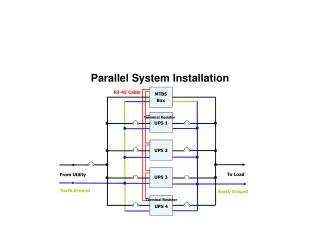
VGD-33 single unit upgrade to parallel system • All single units must work properly • Installation of the external cables and power cords: all should be connected firmly.
VGD-40K3-DTT-0010N single unit PCB setting • PCB P430:CN26 pin 1-2 CN28 pin 1-2 • PCB P386:CN17,CN27,CN37:short • PCB P428:SW2-1:short SW2-2:short CN22,CN23:pin 2-3
VGD-40K3-DTT-0011N parallel system PCB setting • PCB P267: Master UPS:SW1-1:OFF SW1-2:ON Slave UPS :SW1-1:ON SW1-2:OFF • PCB P430:CN26:pin 2-3 CN28:pin 2-3 • PCB P386:CN17,CN27,CN37:open • PCB P428:SW2-1:open SW2-2:open CN22,CN23:pin 1-2
VGD-40K3-DTT-0011N parallel system PCB placement
VGD-40K3-DTT-0011N parallel systemPCB placement photo Bridge rectifier and Golden aluminum shelled resistors Terminals
Caution • All cables should be connected correctly; tighten any loose connection. • There should be no missing or loose parts found on the PC board. If any of the above faulty circumstances occur, please test again after completion of troubleshooting.
CAN BUS setting • Disconnect P430 CN7 connector first • Turn on MST input power • Enter Paramt -> Communic menu for settings • Equipm. Address: 001 Metro Address : 001 CAN Address : 001 • Turn on SLV input power • Enter Paramt -> Communic menu for settings • Equipm. Address: 002 Metro Address : 002 CAN Address : 002
Power-on without Main Power Supply • Turn on MSTand SLV EPO switches, panel ON.ON. Wait about 1 minute and the system will move to INV.Confirm MST panel is indicating Parallel_MST_OKand SLV panel is indicating Parallel_SLV_OKConfirm MST and SLV panel system is working in the INVERTER modeConfirm MST panel and SLV panelsettings via Paramt-> Test PrmPDS=0POV=0PNU=2PBP=2PIV=2MSTpanel OFF, ON, and confirm MST and SLV are all wired to BYPASSTurn off EPO switchTurn off MSTand SLV input power • Disconnect the external CN4 25P connector of SLVTurn on MSTand SLV input powerConfirm MST panel is indicating Parallel_MST_OK and SLV panel is indicating Parallel.BusTurn on EPO switch, panel ON.ONTurn off MSTand SLV input power • Re-connect CN4 25P connector and disconnect the external CN1 and CN2 connectors of SLVTurn on MST and SLV input powerTurn on EPO switch, panel ON.ONConfirm MST panel is indicating Parallel_MST_OK and SLV panel is indicating Parallel.BusTurn off MST and SLV input power
Power-on with Main Power Supply • Confirm the phase is locked • Re-connect two 430 CN7 connectors • Two sets of UPS P428: SW2-1 OFF, SW2-2 ON • Turn on MST and SLV input power • Turn on EPO switch • Wait about 1 minute, two UPS INVERTERs will start operation • Confirm MST and SLV panels are working properly and do not display any error message. MST panel is indicating Parallel_MSTand SLV panel is indicating Parallel_SLV • Turn on MST and SLV battery switches • Turn off input switches simultaneously • Confirm the two sets have the same output waveform, phase and voltage
Power-on with Main Power Supply • EPO, output switch and maintenance bypass switch are confirmed • MST EPOswitch OFF, confirm MST and SLV outputs are all closed • MST EPO switch ON, wait for MSTand SLV to turn to INVERTER • SLV EPO switch OFF , confirm MST and SLV outputs are all closed • SLV EPO switch ON , wait for MSTand SLV to turn to INVERTER • Turn off MST output switch, and confirm MST is switched to SINGLE and SLV is switched to MST • Turn on MST output switch, panelON.ON, and wait for the original MST to be switched from SINGLE to MST • Turn off SLV output switch, and confirm SLV is switched to SINGLE • Turn on SLV output switch, panelON.ON, and wait for the original SLV to be switched from SINGLE to SLV • MST panel OFF, ON, and confirm MST and SLV system is wired to bypass • Turn on MST maintenance bypass switch, and confirm MST and SLV panels are indicating Parallel Sys., Manten. Byp • Turn off MST maintenance bypass switch • Turn on SLV maintenance bypass switch, and confirm MST and SLV panels are indicating Parallel Sys., Manten. Byp • Turn off SLV maintenance bypass switch • Wait for the INVERTER of MST and SLV system to be reset • If all the above functions work properly, the parallel units may be operated properly.