Download

1 / 64
640 likes | 735 Views
Development of a Detector Testing Facility. P. M. Whaley Kansas State University. Overview. Introduction & Motivation Design Considerations Generation I Diffraction System Generation II Diffraction System System Testing Conclusions. K-STATE REACTOR. 1960: Construction Permit

E N D
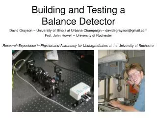
Development of a Detector Testing Facility P. M. Whaley Kansas State University
Overview • Introduction & Motivation • Design Considerations • Generation I Diffraction System • Generation II Diffraction System • System Testing • Conclusions
K-STATE REACTOR • 1960: Construction Permit 100 kW Facility Operating License • 1962: Initial criticality • 1968: 250 kW (with pulsing) license
Reactor Experiment Facilities • 2 Thermal columns • Reflector well • In-core tubes • Beam ports NEBP (piercing) NWBP (radial) • NEBP difficult • SEBP heavily used • SWBP lightly used • NWBP dormant SWBP (radial) SEBP (tangential)
Beam Port Access door seal Inner Plug Outer Plug
K-State Reactor • 2000: Recovery of operating time • 2002: Renewal request (to 1.25 MW) • 2002: SMART Labs installed at K-State
K-State SMART Laboratories • Design & production of radiation detectors • Semiconductor-based radiation detectors • Gas-filled radiation detectors • Major research emphasis on neutron detectors • Opportunities for reactor utilization • Committed NWBP to diffracted beam test facility • Low gamma contamination • Monoenergetic neutrons • Set of facilities for specific processes/functions
Crystal Growth & Testing Labs CdZnTe Growth Condensation/Deposition Lab HgI2 (B) Material Testing HgI2 (A) Surface & Volume Characterization
Processing Labs Crystal Growth Class 1000 Clean Room Processing Vacuum/vapor deposition Ion Mills & Plasma Etching Surface Examination
DESIGN CONSIDERATIONS • Floor loading constraints • Shielding manipulation • Motion controls • Beam intensity • Collimator
Floor Loading Constraints • Beam centerline 30 in. from floor • Bay floor rated to110 lb ft-2 (UBC) • Concrete density nominally 150 psf • Untenable limit for shielding mass • KSU Architect certified design 350 lbf ft-2 • Based on soil compaction • Very limiting, but workable • Elevated shielding minimizes weight
Shielding Manipulation • Manageable with facility equipment • Overhead crane • Manual pallet jack • Powered pallet jack • Elevated • Positioned to shield beam • Reduced floor loading • Stability possible issue
Motion Controls • Limited resources • Computer interface, 2-axis controls • Rotation • Elevation • Adjustable crystal orientation • Experiments show floor extremely stable to impulse loading
Beam Intensity Implications • MB distribution • Peak energy about 50 meV • Harmonics not an issue • approximately 1% flux available • NWBP thermal flux 6x10⁷ n cm-2 s-1 • Estimate 105 n cm-2 s-1 near peak energy available at monochromator
Collimator Design • Beam & monochromator size • Shielding requirements compete with intensity • Radial beam port gamma is severe • Limit consequences of beam port leakage • Options to: • Evacuate flight tube (10% m-1 loss in air) • Install high energy neutron & gamma filters • Install instrumented equipment core-side
GENERATION I SYSTEM • Motion controls/Monochromator • Collimator • Shielding
Generation I Motion Controls • Newport 2-axis controller • Rotation stage • Goiniometer stage • Stages mounted on vibration damper • Labview controls • Scan rotation • Change angle of elevation
Generation I Monochromator • Silicon monchromator cut from thcik, “perfect” crystal
Generation I Shielding • Rotating shield/integral shutter • Apertures for 2 angles & main beam • Elevated platform to minimize mass • Wire enclosure
Generation I Collimator • 1 ½ inch tubes (3) for flight tube variations • Penetrations for inst., gas or cooling lines • Active seal on beam port flange • Thin Al plates seal flight tube in a flange • Connectors for vacuum or helium (1 tube)
Generation I Conclusion • Min. footprint & weight, adequate shielding • Low intensity • Clear peak
Problems • Resources with appropriate knowledge • Personnel • Limited experience • Diffracted beam intensity • Perfect crystal: high resolution, low intensity • Mosaic permits range of energies • Inducing mosaic spread in Si is not trivial • Shielding aesthetics
GENERATION II SYSTEM • Research Assistant • Large collimator • Motion controls & monohromators • Cannibalized Huber theta-2theta stack • LabView Virtual Instrument motion control • Shielding
Graduate Available Soon • Licensed reactor operator • LabView programming • MCNP modeling • 3-D CADD (fabrication & CNC drawings) • Mechanical aptitude & abilities • Maintenance & repairs laboratory equipment • Millwright & pipefitting • ABC News feature “Can I get your picture? My roommate will never believe that a couple of cute girls visited the reactor.”
Gen II Monochromator Stand Monochromator Stage Stage to locate beam
Gen II Monochromators • Pyrolitic graphite • Silicon • Crystal bender
Gen II Collimator Mounted Thin Al window Vacuum connection
Filter Tests Bismuth Sapphire
System Testing • Measurements of spectrum • Monochromator tests for intensity • Filter test for operational characteristics
Monochromator Tests • Silicon • Bent Silicon • Pyrolitic graphite
Conclusions • Facility is essentially complete • Remount area monitor • Finish enclosure • Experiment status sensor • Testing programs in progress
Lessons Learned • Bias of experience affected perceptions • Spectral measurement as a lab exercise • Using a system versus • Building a system • Copper monochromator • Beam extracted from D2O tank adj. to core • Filtering (bismuth & sapphire) perceptions • Not needed • Degrades intensity unacceptably
Lessons Learned • Crystal orientation perception: • Need to have the crystal fully indexed • Flats in Si wafer indicate principle plane • Mosaic spread was not considered necessary
Lessons Learned • Design objectives need to: • Reflect actual needs • Be specified and fixed • Concrete terminology • Concrete is rated for structural load • Architectural load is different • Focus on beam, disregarding background