Download
1 / 74
750 likes | 779 Views
United Arab Emirates University College of Engineering Civil and Environmental Engineering Department Graduation Project II. Reliability of Non-Destructive Tests for Evaluating Concrete Quality. Done By: ID#: Alhassan Mohammed 200440287 Ahmed Al Samri 200415474

E N D
United Arab Emirates University College of EngineeringCivil and Environmental Engineering DepartmentGraduation Project II Reliability of Non-Destructive Tests for Evaluating Concrete Quality Done By:ID#: Alhassan Mohammed 200440287 Ahmed Al Samri 200415474 Yaser Al Nuaimi 200415464 Nader Al Zarouni 200418635
Introduction • Reinforced concrete structures are subjected to deterioration. • Deterioration affect integrity, stability and safety of reinforced concrete structures. • This project is about the Reliability of Non-Destructive Tests for Evaluating Concrete Quality for RC structures.
approach for the graduation project • Review and study different NDT’s. • Understand procedures used for each NDT’s. • Understand factors & limitations affecting results of each NDT’s. • Apply concrete mix design to design various mixes with different grades.
approach for the graduation project • Apply different NDTs on the casted mixes to check their reliability. • Enhance the obtained results through combining several NDT’s together. • Test the obtained result on concrete of unknown strengths brought from real life project as a verification of the project end result.
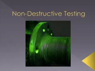
What is meant by Non-Destructive Tests? • Set of tests used for evaluating the quality of hardened concrete. • Doesn’t affect the integrity of structural elements of buildings. • Doesn’t impair the intended performance of the element or member under test.
Achievements in G.P 1 • There are verity NDTs.
Alternatives in GP1 • The most common NDTs to evaluate concrete quality.
Alternatives in GP1 • Schmidt Hammer test
Alternatives in GP1 • Ultrasonic Pulse Velocity tests are performed to assess the condition of structural members with two-sided access such as elevated slabs, beams, and columns. • Use the UPV device available in the college laboratory.
Alternatives in GP1 • Coring test machine available in COE Laboratory.
Background theory about NDTtest Hammer Rebound test • Ultrasonic Pulse testing Coring Covermeter
Ultra Sonic Pulse Velocity Test (UPV) • Before using the UPV instrument, it is necessary to calibrate it using the calibration polymer bar to ensure accurate findings. • The transducers of the instrument (transmitter and receiver) were lubricated using lubrication material.
Ultra Sonic Pulse Velocity Test (UPV) • The readings are to be plugged in a formula to calculate the desired concrete quality (strength).
Rebound hammer test • Before using the Rebound Hammer device, the settings of the device should be adjusted according to the situation. • The position of the instrument during testing should be identified in the device for accurate results • Concrete specimens are fixed in place to avoid movement during testing.
Rebound hammer test • 10 readings are taken in an area of 10 cm X 10 cm. • The device will give an average of the recorded rebound numbers. • The rebound numbers are plugged in equations for concrete quality determination.
Coring test • Get standard cores from plain concrete slabs , and use them in Compressive Strength Test. • Fixing the drilling machine on the ground. • Cores are available in different sizes (mainly 7 cm and 10cm). • The cores were obtained at different locations from the unreinforced concrete slabs.
Coring test • Measured the dimensions of the cores. • A sulfur cap cover the top and bottom of each core prior to Compressive Strength Test. • The obtained loads were recorded to be used in actual concrete quality determination later on.
Compressive strength test • After finishing all other tests, the specimens (cubes & cores) are ready for Compressive Strength Test. • Each specimen need to be fixed in the compressive machine in order to applied load on it.
Compressive strength test • The load is applied gradually. • Failure load of the specimen is recorded. • For cylinders, it’s important to cover the rough surfaces by sulfur capping to insure uniform distribution of applied load.
Concrete mix design methods • Trial and error method; • Empirical method; • British Standard Method (BS 8328); • American Concrete Institute method (ACI-211.1-91).
British Standard Method (BS 8328) • Different grades of concrete: 25 MPa, 40 MPa, and 60 Mpa are to be designed. • Some data were assumed to be given based on the available materials and the surrounding environments in the lab : • 5% defects allowed • Very good degree of control • Slump =60mm • Ordinary Portland Cement (OPC) • Crushed stones
Sieve analysis • Sieve analysis was applied to coarse aggregates and fine aggregates. • 50% of aggregates was course while the other 50% was fine. • Coarse aggregate was considered as a mix of large course aggregates (50%) and smaller course aggregates (50%) • Fine aggregates was 50 % conventional sand and 50% dune sand.
Sieve analysis • The expected findings from sieve analysis process are: • Aggregate grading curve. • Nominal Maximum Size (NMS) • which is the sieve size through which 95% of the aggregate passed was determined (20mm). • Fineness Modulus (FM). • which is obtained by adding the sum of the cumulative percentages by mass of a sample aggregate retained on each of specific series of sieves and dividing the sum by 100 (sand=4, dune sand=0.9).
Sieve analysis For CourseAggregates. Aggregate Grading Curve For CourseAggregates. For Conventional sand.
Sieve analysis For Dune Sand. Aggregate Grading For Dune Sand.
Mix design • Determining Target Mean Strength (Fm)
Determining the water content • Water content= 210 lit
Determining the fresh density of concrete • The fresh concrete density =2400 kg/m3.
Determining dune sand % • X= sand • Y= dune sand • X=0.55 • Y=0.45
Mix proportions and quantities for 1 m3 • For 60 MPa • For 40 MPa
Mix proportions and quantities for 1 m3 • For 25 MPa
Determining the volume of form works • Standard Cube Dimension: 15 X 15 X 15 cm • Slab Dimensions: 50 X 50 X 15 cm • The volume for all mixes was determined to be 0.2 m3
Needed Quantities • The quantities required to cast 18 cubes and 12 slabs are tabulated below.
Material preparation • Weighting Materials • Formwork Preparation • Steel Cutting
Tests results • Mix1
Tests results • Mix 2
Tests results • Mix 3
Al reem ready mix concrete samples • It is required to have unknown concrete samples to be tested in the laboratory after doing the analysis to check the project’s finding. • Last week 88 concrete cubes were brought from Al Reem Ready Mix in Al Reem Island. • The cubes are to be tested using the final project finding (equation) and the results are to be compared to the actual compressive strengths obtained by compressive strength test.
Predicting Compressive Strength Using Ultrasonic Pulse Velocity Test • UPV test is conducted on various concrete cubes with variable qualities in order to evaluate its quality. • No direct relationship between UPV and compressive strength.
Relation between UPV and measured compressive strength • Wide scatter of the data points. • UPV ranges between 4.0km/sec and 5.5km/sec while the measured strength has a wider range (from 25MPa to 95MPa). • UPV would not be a sensitive method to predict compressive strength.
relation between the actual strength and the strength predicted by UPV test • 90 points was used to construct the relationship between the UPV and the measured compressive strength. • Where; fc =Predicted compressive strength (MPa). V =Ultrasonic Pulse Velocity (km/sec). • The coefficient of determination of the obtained relationship (r2) is 0.258 weak relation.