Download

1 / 20
210 likes | 328 Views
Automated Design and Prototyping of Macro and Micro Compliant Mechanisms.

E N D
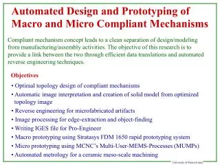
Automated Design and Prototyping of Macro and Micro Compliant Mechanisms Compliant mechanism concept leads to a clean separation of design/modeling from manufacturing/assembly activities. The objective of this research is to provide a link between the two through efficient data translations and automated reverse engineering techniques. Objectives Optimal topology design of compliant mechanisms Automatic image interpretation and creation of solid model from optimized topology image Reverse engineering for microfabricated artifacts Image processing for edge-extraction and object-finding Writing IGES file for Pro-Engineer Macro prototyping using Stratasys FDM 1650 rapid prototyping system Micro prototyping using MCNC’s Multi-User-MEMS-Processes (MUMPs) Automated metrology for a ceramic meso-scale machining
Performance Specifications Synthesis Solution Refined Design Solution Reverse Engineering Meshed Model for Analysis Solid Model from the Optimized Device CAD model from the macro prototype Design Mask Layout for Microfab. Digital Format for SFF or CNC Refined Prototype Digital Interface Macro Prototype Micro Prototype Solid model from microscopic images Fabrication/Prototyping Design and Prototyping of Macro & Micro Compliant Mechanisms
Compliant Designs Macro • Compliant mechanisms (Midha et al., 1988-98) effectively utilize elastic deformation of structures to transform motion and force. • Compliant designs are comprised of flexible and strong part(s) as opposed to the conventional rigid and strong parts. • Compliant designs restrict the design space without compromising kinematic functionality. • Ease manufacturing and assembly • Minimum number of parts • Minimal or no assembly at all • Well-suited for CNC machining and SFF Micro Clean separation of design and manufacturing is possible. Applicable to any scale - macro, meso, and micro.
Designing Compliant Mechanisms They should be flexible to deform easily They should also be stiff to sustain loads Measure of flexibility: mutual potential energy = Measure of stiffness : strain energy = Multi-criteria optimization formulation: For a specified functional behavior, it is possible to obtain an optimal solution using either the super structure approach or the material density approach. The Objective: Convert the optimal image to a manufacturable form without overly compromising the functionality and performance.
Design Parameterizations Super structure approach Specifications Solution Material density approach
Algorithm for model extraction We utilize a six step method for creating a solid model from either a photo or a synthesized optimal design. We rely on two primary assumptions: • the images of interest have high contrast • the images are not cluttered with extraneous visual data Each step utilizes simple image processing techniques. Image filtering Edge detection Object characterization Arc and line extraction Model creation Manufacturing
1. Image Filtering and Thresholding • The synthesized designs are generally coarsely pixelated. We use a blurring operation to smooth the image • A simple contrast threshold is then used to separate areas with material from ones without 2. Edge Detection • We use a simple binary filter to extract edges • Each edge is guaranteed to be only a single pixel wide 3. Object Extraction • Assume that all objects have closed loop boundaries • Scan the image to find a boundary, and then follow that boundary to identify an object • The connectivity of each object is stored for further processing
4. Arc and Line Extraction • Each object is analyzed to generate a planar model based on best fit arcs and lines • Algorithms inspect groups of adjacent points to see if arcs or lines can approximate points to within a given tolerance 5. Model Creation • Each object is resolved into a connected set of lines and arcs and written to an IGES file • The IGES file can be read by a variety of programs for FEA/FEM, solid modeling, etc. We import into Pro/Engineer and generate a 3-D model by extrusion 6. Manufacturing • A macro prototype is then generated from the solid model • Using a Fused Deposition Modeling (FDM) machine, a plastic prototype can be generated (it is slightly brittle) • Using a CNC machining center, more robust prototypes can be machined out of polystyrene or aluminum
Experimental Set-up for Optical Imaging CCD Camera Optical Microscope Magnified image
Edge Extraction from 2-D Images Image from the optical microscope After edge extraction The lack of sharp edges corresponding to the actual structure poses a challenge in extracting the correct topology.
Verification with Test Images Extracted circular segments ported into Pro-E in IGES format Test image with circular curves Extracted line segments ported into Pro-E in IGES format Test image with sharp edges
From Fabricated MEMS Device to a Solid Model Optical microscope image of a compliant micro crimper After edge extraction 5 µm
From Fabricated MEMS Device to a Solid Model (cont’d) Extruded solid model ready for analysis IGES model exported into Pro-E with line and arc segments
From Fabricated MEMS Device to a Solid Model (cont’d) FDM prototype of compliant gripper Unloaded configuration Deformation under loading
From Optimized Compliant Topology Image to a Solid Model Similar image processing techniques can be used to generate solid models for synthesized optimized compliant devices Topology optimization does not give the shape precisely in both the “super structure” and “material density” approaches. Designer’s intuition is needed to interpret the image and to obtain a manufacturable form. Simple image processing is inadequate to capture the correct quantitative behavior of the optimized compliant topology.
From Optimized Compliant Topology Image to a Solid Model Optimized compliant topology using material density design parameterization IGES model with line and arc segments Blurring, image processing, edge extraction, and object finding
From Optimized Compliant Topology Image to a Solid Model Solid model ready for rapid prototyping and/or detailed 3-D analysis Suitable flexibility is not obtained.
Future Work Use shape optimization to refine the topology image, with stress and manufacturability constraints. Combine image processing directly with shape optimization to automate the entire process. Study the effect of tolerances on the image processing, particularly as it affects stiffness and deflection characteristics. Generate macro prototypes from MEMS mask layouts, giving designers the ability to easily visualize microfabricated devices. Utilize feature extraction techniques for non-invasive, vision-based force-sensing of compliant MEMS devices, such as grippers and clamps. Perform visual part inspection and tolerance checking on critical components using microscope images Use stereo images to generate real 3-D solid models
Fabricating macro prototypes from MEMS mask layouts Two views of a 3-D macro prototype generated from the mask layouts of a Sandia wedge micromotor