Download
1 / 24
340 likes | 941 Views
5 Films and Luminescent Screens. Film is not a good medium for recording x-rays directly; only 2-3% of x-rays are absorbed by the film. 1: Use fluorescent screen to convert x-rays to light. 2: Record light with film. Flourescent Screens reduce patient exposure to x-rays.

E N D
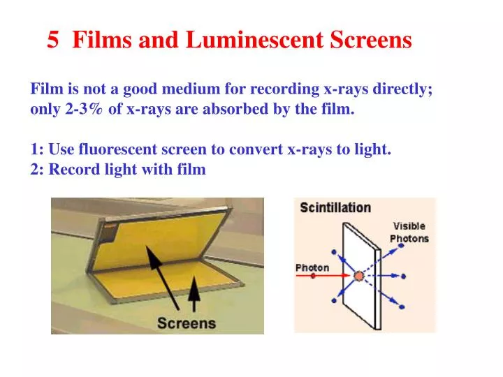
5 Films and Luminescent Screens Film is not a good medium for recording x-rays directly; only 2-3% of x-rays are absorbed by the film. 1: Use fluorescent screen to convert x-rays to light. 2: Record light with film
Flourescent Screens • reduce patient exposure to x-rays. • film is more sensitive to light than x-rays, • converting x-rays to light permits less x-ray dosage to create an • acceptable film image. • Scintillation effect: • · A high-energy photon (x-ray) is converted into low-energy • photons (visible light) • Phosphor, Cesium Iodide, and Selenium are good scintillators • It is important that intensifying screens match film sensitivity.
Screen Construction • · External protective coating • · Bonded phosphor crystals • · Plastic base support • A thin layer of reflecting material • ·Calcium Tungstate emits blue light photons. • Rare Earth emits green light photons
Screen Speed The "speed" of an intensifying screen is determined by the thickness of the fluorescent phosphor layer. Fast Screen Has a relatively thick phosphor layer with: · Increased image brightness · Decreased image resolution · Reduced image blurring (caused by patient movement) · Shorter exposures and reduced patient dose Slow Screen Has a relatively thin phosphor layer with: · Decreased image brightness · Increased image resolution Longer exposures and increased patient dose
Radiographic Film Construction Film is not just a simple piece of cellulose or plastic. Modern film is about 0.2 mm thick and is clear (or tinted blue for easier viewing). Film must: · Be stiff enough to snap into a light box for viewing · Have good dimensional stability so that the image won't distort over time · Absorb very little water (important during processing)
Emulsion is the active layer. It absorbs radiation (x-ray or light) and records the latent image. The emulsion consists of microscopic crystals of silver halide suspended in gelatin. The emulsion is covered with a protective T coat (hard protective coating) It is sensitive to visible and ultraviolet light, and ionizing radiation.
The Photographic Process X-ray film images are produced primarily by the visible light from the intensifying screen. The process of photographic imaging is a three stage process: 1: Form a latent image ( transient until developed) 2: Chemical development of silver grains to form permanent image 3: Fixing of image to remove developer chemicals and makes image permanent
Forming a Latent Image The radiographic (or latent) image is created on the film emulsion by the exposure to either ionizing radiation or light. The photons from either the x-ray beam or from the intensifying screen act on the silver halide in the emulsion to create an image. Gurney and Mott produced the accepted hypothesis of the formation of the latent image
Stage 1:X-rays release electron from Ag Br ( silver bromide) grain. Electron is free to migrate across grain. AgBr +photon Ag+ + Br- + e- Stage 2:Electron is trapped n dislocations or AgS impurities in grain.
Stage 3:The trapped electron attracts mobile Ag+ ions in the crystal The Ag + ions become neutral silver metal at the trapping site. Ag+ + e- Ag The trapping site grows and forms a speck of silver metal on the grain. Grains exposed to radiation which form over 4 or 5 silver atoms form the latent or hidden image.
Development • Latent image is composed of grains with some specks of Ag • Developer reduces AgBr to silver metal • Developers are hydroquinone +phenidone • QH2 + 2AgBr Q + 2Ag + 2H+ 2Br-
Film Processing Developingamplifies the L latent image by a factor of hundreds of millions to form a visible metallic silver (black) image. 2. Fixing removes unexposed silver halide crystals and hardens the gelatin. This prevents the image from fading over time. 3. Washing removes all chemicals and prevents discoloration. Drying allows the film to be handled.
Film Characteristics Densitometers compare transmitted intensity ( It) to the incident intensity (Io). Transmission = It /Io Density of Optical Density = log ( 1/T) Virtually no sensitometer directly reads density! ·Density measures the blackening of a film. ·Contrast is the ability to display a range of densities ·Speed (or Sensitivity) is the ability to respond to light Latitude is the range of relative exposures that will produce density within the accepted range for diagnostic radiology.
Optical densities are additive! Io D1 = log (Io/I1) I1 D2 =log (I1/I2) I2 D = log (I2/Io) = D1+D2
Measuring Film Density Plot characteristic curve Sensitometer exposes film to step wedge Densitometer measure film transmission
H-D Curves The H-D curve is a plot of Density versus Log Relative Exposure. Exposure is the product of the beam current and exposure time. The HD curve consists of three basic parts: · Toe: · Shoulder: · Intermediate density region: Radiographic exposures fall within he intermediate density region In your job, you will use an H-D curve to evaluate whether film processing is good or bad. You must do this before finding fault with the x-ray system hardware.
Base Density is the density of the film without exposure to radiation Fogging, or fog density, can be caused by: · Film age · Background radiation · Chemical vapors · Warm temperatures Fogging reduces film contrast. Base + Fog should have a density less than 0.25.
Film contrast Difference in densities corresponding to unit change in exposure. It is affected by: Film type · Processing conditions · Density level · Fog level in the film The slope (or steepness) of the characteristic curve is related to film contrast by g = tan-1 ( slope of HD curve) = tan-1 ( density/ log exposure)
Film Speed(or sensitivity) is the film's ability to respond to radiation, such as light or ionizing radiation. Fast film (high-speed) takes only a short exposure to darken or blacken the emulsion. Faster film reduces blurring caused by motion, but the image may appear noisy or grainy. Slow speed film requires a longer exposure. Slower film shows finer detail, but requires a higher x-ray dose. The position of the characteristic curve along the horizontal axis indicates the relative speed of the film. Latitude, or dynamic range is the exposure range of film over which acceptable densities are produced.