Download
1 / 72
720 likes | 811 Views
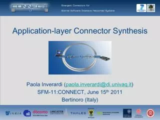
Application-layer Connector Synthesis. Paola Inverardi ( paola.inverardi@di.univaq.it ) SFM-11:CONNECT, June 15 th 2011 Bertinoro (Italy). Outline. Introduction background notions: protocol, interoperability, etc. coordinator concept vs mediator concept Application-layer Coordinators

E N D
Application-layer Connector Synthesis Paola Inverardi (paola.inverardi@di.univaq.it) SFM-11:CONNECT, June 15th 2011 Bertinoro (Italy)
Outline • Introduction • background notions: protocol, interoperability, etc. • coordinator concept vs mediator concept • Application-layer Coordinators • synthesis of centralized coordinators [SCP08] • synthesis of distributed coordinators [JSS08a] • synthesis of coordinators for real-time systems [TACAS07] • synthesis of coordinators for evolving systems [JSS08b] • Application-layer Mediators • synthesis of emerging mediators for ubiquitous systems [ISOLA10, RSPHDT10, WICSA/ECSA09] • Related Works • Conclusion
Introduction • The Ubiquitous Computing environment is populated by a wide variety of heterogeneous Networked Systems (NSs), dynamically appearing and disappearing • Heterogeneous protocols may be willing to cooperate in order to reach some common goal even though they meet dynamically and do not have a priori knowledge of each other • Challenge:how to automatically achieve the interoperability between heterogeneous protocols in the Ubiquitous Computing environment
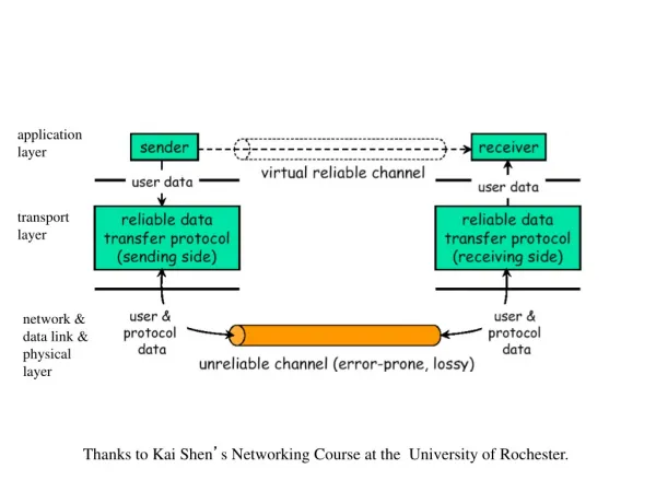
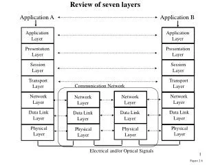
Modeling Application-layer Protocols • The term protocol refers to interaction protocols or observable protocols • We consider application-layer protocols (as opposed to middleware-layer protocols) • behavior of a system in terms of the sequences of messages at the interface level, which it exchanges with other systems • the notion of protocol abstracts from the content of the exchanged messages, i.e., values of method/operation parameters, return values, etc. • Our focus is on harmonizing the behavioral protocol (e.g., scheduling of operation calls) of heterogeneous NSs rather than performing mediation of communication primitives or of data encoding/decoding (i.e., middleware-layer mediation)
Modeling Application-layer Protocols: an example • By using Labeled Transition Systems (LTSs) • Input actions, e.g., Acknowledge, model • methods that can be called; • receiving messages; • return values. • Output actions, e.g., Authenticate, model • method calls; • message transmission; • exceptions. A Photo Sharing producer
Interoperability • The ability of heterogeneous protocols to communicate and correctly coordinate to achieve their goal(s) • Communication expressed as synchronization • two protocols communicate if they are able to synchronize on common actions • for application-layer protocols, it goes beyond single basic synchronizations and may require a well defined sequence of synchronization to be achieved (a primary from of coordination) • E.g., sendItems <-> receiveItems(simple case) sendItems <-> receiveItem … receiveItem(more complex case) • Coordination expressed as the achievement of a specified goal • two protocols succeed in coordinating if they interact through synchronization according to the achievement of their goal(s) • Goal usually specified in some automata-based or temporal logic formalism
The Interoperability Problem • It concerns the problem of both enabling communication and achieving correct coordination (w.r.t. the specified goal) • Solution: automatic synthesis of application-layer connectors • Automatic coordinator synthesis (our past research) • the main focus is on addressing correct coordination by assuming the communication problem already solved • Automatic mediator synthesis (our current research in CONNECT) • it focuses on the whole interoperability problem, i.e., addressing communication + correct coordination
desired behavior specification Coordinator concept already communicating black-box components their interaction may deadlock… …or violate a specified desired behavior Component 1 Component 3 Component 2 solution Component 1 Component 3 the coordinator is an additional component synthesized so as to intercept all component interactions in order to prevent deadlocks and those interactions that violate the specified desired behavior Coordinator Component 2
The need for Coordinators:the Shared Resource scenario AlternatingProtocol desired behavior specification Deadlock! Screenshots from the SYNTHESIS tool. If you are interested on it, attend the lab session…
Mediator concept • In the Ubiquitous Computing (UbiComp) domain, the granularity of a system shifts from the granularity of a system of components (as in the CBSE domain) to the one of a System-of-Systems (SoS) • An SoS is characterized by an assembly of a wide variety of building blocks. Thus, in the UbiComp domain, enabling communication between heterogeneous NSs regardless, at a first stage, possible coordination mismatches, becomes a primary concern • This introduces another specific notion of connector, i.e., the notion of mediator seen as a communication connector
The need for Mediators:the Photo Sharing Scenario Infrastructure based implementation Peer-to-peer based implementation
Outline • Introduction • background notions: protocol, interoperability, etc. • coordinator concept vs mediator concept • Application-layer Coordinators • synthesis of centralized coordinators [SCP08] • synthesis of distributed coordinators [JSS08a] • synthesis of coordinators for real-time systems [TACAS07] • synthesis of coordinators for evolving systems [JSS08b] • Application-layer Mediators • synthesis of emerging mediators for ubiquitous systems [ISOLA10, RSPHDT10, WICSA/ECSA09] • Related Works • Conclusion
Automatic Synthesis ofFailure-Free Coordinators (FFC) • Communication issues are assumed to be already solved • protocols are already able to synchronize, although deadlocks in their interaction can occur or their interaction could not satisfy specified behavioral properties • A specific instance of the interoperability problem • given a set of interacting components, C, and a set of behavioral properties, P, automatically derive a deadlock-free assembly, A, of these components which guarantees every property in P, if possible • A is a composition of the components in C plus a synthesized coordinator • the coordinator is an additional component that controls the message exchange to prevent possible deadlocks and those interactions violating the properties in P • Four different approaches (following slides) • centralized coordinator, distributed coordinator, for evolving systems, for real-time systems
Automatic Synthesis of Centralized FFC– Basic Idea – • A simple software architecture structure which exploits the separation between functional behavior and Integration/Communication behavior. • Extra information at component level: component Assumptions. • Our approach: • detect software anomalies • prevent software anomalies • guarantee given coordination policies (behavioral properties)
Automatic Synthesis of Centralized FFC– Modeling – • Component behaviour modelled using finite state machines • Integration through parallel composition of component models • In the context of CCS: • Components: sequence and choice operators E.g. Server = call.service.return.Server • Integration: parallel composition and restriction operators E.g. (C1 | C2 | ... | Cn) / L • Deadlock: (C1 | C2 | ... | Cn) / L can reach a state where no actions are possible
Automatic Synthesis of Centralized FFC– Assumptions – • Component requirement on its environment in order to guarantee a property in a specific integration context • In a sense we are enhancing component semantics • In our case we use: “My context never blocks me” or in other words “If I can perform action a, my context must be able to perform action a” • Assumptions modeled in the same way as components
a Coordinator Free Architecture (CFA) is a set of components directly connected in a synchronous way in CCS : (C1 | C2 | ... | Cn) \ Ui=1..nActi Automatic Synthesis of Centralized FFC– Background notions (cont’d) – • Coordinator Free Architecture (CFA) Component 1 Component 2 channel channel Component 3
top Component 1 bottom channel 1 REQUEST top NOTIFICATION Coordinator bottom channel 3 channel 2 top top Component 2 Component 3 bottom bottom Automatic Synthesis of Centralized FFC– Background notions – • Coordinator Based Architecture (CBA) in CCS: (C1[f1] | C2 [f2] | ... | Cn[fn] | K) \U i=1..nActi[fi] K is the synthesized connector, fi a suitable relabeling function
AC-Graph: the inner knowledge msg1? msg1C msg2C msg2? msg1 msg2 msg2 msg1 Knowing the composition mechanism and the property msg3? msg3C AS-Graph: assumptions on the environment msg3 msg3 Knowing the characteristics of the coordinator EX-Graph: assumptions on the coordinator Automatic Synthesis of Centralized FFC– Component Local Views – How to model all the local views from the component perspective?
C1 C2 Coordinator C3 msg2C2 msg2C1 msg2? msg1C2 msg1C1 msg1? msg1? msg1? msg1C3 msg2? msg2? msg2C3 coordinator graph obtained by the unification of the EX-Graphs msg1C1 msg1C3 msg2C1 msg2C3 msg1C2 msg2C2 msg1C3 Automatic Synthesis of Centralized FFC– Component Local Views Unification – is based on a usual first-order unification algorithm
Table Table Deadlock Scenario: • component Philosopher1 requests and gets the resource of component Fork1; • component Philosopher2 requests and gets the resource of component Fork2; • component Philosopher1 requests and waits for the resource of component Fork2; • component Philosopher2 requests and waits for the resource of component Fork1; Coordinator Coordinator Free Architectural View Coordinator Based Architectural View Automatic Synthesis of Centralized FFC– Deadlock Freedom: an example – Assigning a deadlock-free routing policy to the coordinator it is possible avoids the deadlock scenario. • Dining Philosophers Problem:
local views of each component Component 1 Component 3 Component 1 Component 1 Component 3 Component 3 Coordinator code (assembly code) (no-op) Coordinator Coordination policy deadlock-freeness Deadlock-freeCoordinator Failure-freeCoordinator Component 2 Component 2 Component 2 Coordinator Based Architecture Deadlock-free Coordinator Based Architecture Failure-free Coordinator Based Architecture Automatic Synthesis of Centralized FFC– 3-step method – Coordinator Free Architecture Component 1 Component 3 Component 2
Automatic Synthesis of Centralized FFC– running example: inputs – CFA P C1 and C2 has to interact by following an Alternating Interaction Protocol C
Automatic Synthesis of Centralized FFC– running example: enforcing deadlock freedom – Deadlock-free Coordinator No-op Coordinator
Automatic Synthesis of Centralized FFC– running example: enforcing failure-freeness – • - The Failure-free Coordinator is a refinement • of the deadlock-free one that obeys the • alternating protocol specified by P • It is obtained by performing a suitable notion • of synchronous product between P and the • deadlock-free coordinator
class K : public IC3 { // stores the current state of the coordinator private static intsLbl; // stores the current state of the // property automaton private static intpState; // stores the number of clients private static intclientsCounter = 0; // channel's number of a client private intchId; // COM smart pointer; is a reference to // the inner C3 object private static C3* c3Obj; ... // the constructor K() { sLbl = 0; pState = 0; clientsCounter++; chId = clientsCounter; c3Obj = new C3(); ... } (k0,p0) • These interfaces export • three services: • - method1 (affected by the policy) • method2 (affected by the policy) • method3 (a simple delegation) ?C3.method1_1 !C3.method1_3 ?C3.retValue1_3 !C3.retValue1_1 (k9,p1) C1 C3 C2 COORDINATOR COMPONENT Automatic Synthesis of Centralized FFC– running example: FFC’s code synthesis – HRESULT method1(S_DAda) { if(sLbl== 0) { if((chId== 1) && (pState== 0)) { pState = 1; sLbl = 9; return c3Obj->method1(da); } } … /* otherif-statementsforeach FFC state in whichitispossible toperform method1 */ … returnE_Handle; } • By visiting the LTS modeling the FFC protocol, the actual code implementing the coordinator component is automatically derived • C++ implementation for COM/DCOM component-based systems (centralized FFC) – in this example… • AspectJ implementation for J2EE applications, i.e., EJB component-based systems (distributed FFC) – in the following slides…
Outline • Introduction • background notions: protocol, interoperability, etc. • coordinator concept vs mediator concept • Application-layer Coordinators • synthesis of centralized coordinators [SCP08] • synthesis of distributed coordinators [JSS08a] • synthesis of coordinators for real-time systems [TACAS07] • synthesis of coordinators for evolving systems [JSS08b] • Application-layer Mediators • synthesis of emerging mediators for ubiquitous systems [ISOLA10, RSPHDT10, WICSA/ECSA09] • Related Works • Conclusion and Future Perspectives
black-box components standard communication synchronous channels coordination wrappers asynchronous channels Automatic Synthesis of Distributed FFC– the reference architectural style – additional communication f1 f2 Distributed CBA f4 f3 a demo for this approach, and related SYNTHESIS tool, will be given during the lab session…
Automatic Synthesis of Distributed FFC– first step of the method – Coordinator-FreeArchitecture(CFA) CentralizedCoordinator-BasedArchitecture (Centralized CBA) C1 C2 Centralized Coordinator C3 C4 based on the previous approach
Automatic Synthesis of Distributed FFC– second step of the method – CentralizedCBA C1 C2 1) Deadlock-freedom analysis Centralized Coordinator (LTS) 2) Desired behavior analysis C3 C4 Desired behaviorspecification: LTS-based notation
Automatic Synthesis of Distributed FFC– second step of the method – DistributedCBA • Distributed Coordinator(i.e., set of wrappers) • Deadlock free • Desired behavior satisfying • (automatically distributed by Synthesis) C1 C2 W1 W2 Centralized Coordinator W3 W4 C3 C4
C1 C1 C2 C2 C3 C4 C1 C2 C3 C4 W1 W2 W3 W4 C3 C4 Automatic Synthesis of Distributed FFC– summing up –
Automatic Synthesis of Distributed FFC– running example: inputs – C1C2 C3C4 A possible deadlock can occur if both C3 and C4 perform the action at the right of the initial state s0 P C3 cannot access resource C2 without performing authentication, first
Automatic Synthesis of Distributed FFC– running example: no-op centralized coordinator – Red nodes represent possible occurring deadlocks
Automatic Synthesis of Distributed FFC– running example: Last Chance (LC) states elicitation – when C3 is willing to perform action p1, its wrapper, FC3, must ask permission to the other wrappers in order to discover whether the global state is different from S12 (C3 is allowed to perform p1) or not (C3 is not allowed to perform p1) E.g., S12 = <S3,S0,S0,S9>, FC3 will ask to FC1, FC2, and FC3, if their supervised components are in, or will reach, the statesS3, S0, and S9, respectively
Automatic Synthesis of Distributed FFC– running example: Updating and Allowed (UA) actions elicitation – each wrapper knows what are the property states from which it is allowed to perform some action, which action, and the related target states
Automatic Synthesis of Distributed FFC– pseudo-code for the implementation of the wrappers – • A wrapper FC establishes when its controlled component Ccan move (by cooperating with the other wrappers FH): • The component C must be active (with respect to P) • Before moving by means of actiona, FC checks in FCLC if ais an action that can lead to forbidden states • If it is, FC has to ask the permission to the other component wrappers before performinga • If not, FC allows Cto perform awithout asking anything • If C is allowed to perform actiona, FC has to check in FCUA whether a makes P change its state or not • If it does, FC has to send a block message to all the wrappers whose supervised component cannot move (with respect to P) and an unblock message to all the ones whose supervised component was blocked, but now can move because of the new state of P • When FCasked, to some FH, for the permission of performing an action • FH answer to FC whenever FHis in, or will reach, a state different from the one for which FHhas been enquired by FC • otherwise, FH does not answer hence attempting to block FC
Automatic Synthesis of Distributed FFC– running example: wrappers’ AspectJ code synthesis – • for each action, a pointcut is defined in order to intercept the corresponding method call • for each action, an advice after() is defined in order to update the current local state (i.e., state), the property state (i.e., ps), and to inform all the other wrappers of the updated current local state (i.e., Notify()) For instance, the wrapper for C3 (i.e., for Client1) is an Aspect instrumenting the .class of C3 as follows: e.g., after() returning (int res) : Connect_action() { if((state.intValue() == 0) && (res != -1)) state = new Integer(0); if((ps.read() == 0) && (res != -1)) ps.write(1); Notify(); } e.g., pointcutConnect_action() : call(int Server2.Connect(..));
Automatic Synthesis of Distributed FFC– running example: wrappers’ AspectJ code synthesis – • an advice around() is used to enforce the specified desired behavior, it is defined for any component action that is a negative action on the property automaton • for each action a stored into the last chance states table, an advice before() is defined in order to eventually unblock possible wrappers still waiting for the permission to proceed and, in turn, ask for the permission to proceed on a e.g., intaround() : FreeP1_action() { if((ps.read() == 0)) { return -1; } returnproceed(); } e.g., intaround() : p1_action() { if((ps.read() == 0)) { return -1; } returnproceed(); } e.g., before() : p1_action() { Notify(); AmIAllowed(); }
Outline • Introduction • background notions: protocol, interoperability, etc. • coordinator concept vs mediator concept • Application-layer Coordinators • synthesis of centralized coordinators [SCP08] • synthesis of distributed coordinators [JSS08a] • synthesis of coordinators for real-time systems [TACAS07] • synthesis of coordinators for evolving systems [JSS08b] • Application-layer Mediators • synthesis of emerging mediators for ubiquitous systems [ISOLA10, RSPHDT10, WICSA/ECSA09] • Related Works • Conclusion and Future Perspectives
Automatic Synthesis of FFC for Real-Time Systems– aims – • Propose a lightweight component model • to express real-time interaction properties • Develop a method to check incompatibilities between components (due to timing and/or protocol mismatch) and to produce FFC incrementally • Implement this method inside a tool chain
Automatic Synthesis of FFC for Real-Time Systems– component model – • A component has input ports (a), output ports (b), and one clock port (w1) • Interaction between two connected components is synchronous • reading and writing operations are blocking • The clock port is a special input port (modeled as an element of {0,1}) that tells whether the component is enabled (1) or disabled (0) • connected at the instantiation to a periodic clock
Automatic Synthesis of FFC for Real-Time Systems– component interaction protocol – • The interaction protocol is specified as a LTS with actions of the form: xl{u}[i,j] • action label (a is a read / b is a write) xl{u}[i,j] • controllability tag • duration (local time units) • latency (global timeunits) • The component is instantiated with a periodic clock (e.g. (10)); when disabled it can only let the global time elapse, when enabled it can also perform an action
Automatic Synthesis of FFC for Real-Time Systems– component semantics – • Latency is a QoS requirement • Duration is a constraint of the execution platform each state is labeled with the global time instant modulo the periodic clock’s length (e.g.,<s4,0> and <s5,1>)
Automatic Synthesis of FFC for Real-Time Systems– an example – • Assembly put together components and specify ports renaming • Here, the interaction protocols do not match • Proposal: to generate automatically a correct-by-construction and bounded coordinator in order to solve protocol/latency/duration/clock inconsistencies
Automatic Synthesis of FFC for Real-Time Systems– method overview –
Automatic Synthesis of FFC for Real-Time Systems– running example – Semantics LTS of <C3,(11)> Semantics LTS of <C4,(10)>
Automatic Synthesis of FFC for Real-Time Systems– running example: mismatch detection – • We compute the synchronous parallel composition of the LTSs • Deadlocks are sink states in this parallel composition • We use CADP to detect such sink states • In the example, the initial state of the synchronous product is a sink state:
Automatic Synthesis of FFC for Real-Time Systems– running example: component’s expectation – • For each component, we compute one Petri Net (PN) modeling what the component expects from its environment (i.e., the other components plus the environment)
Automatic Synthesis of FFC for Real-Time Systems– running example: unification PN – • We build the causal dependencies (read/write) by unifying the pending places • And we compose synchronously the time-elapsing transitions (only the firable ones are shown)