Download
1 / 46
460 likes | 606 Views
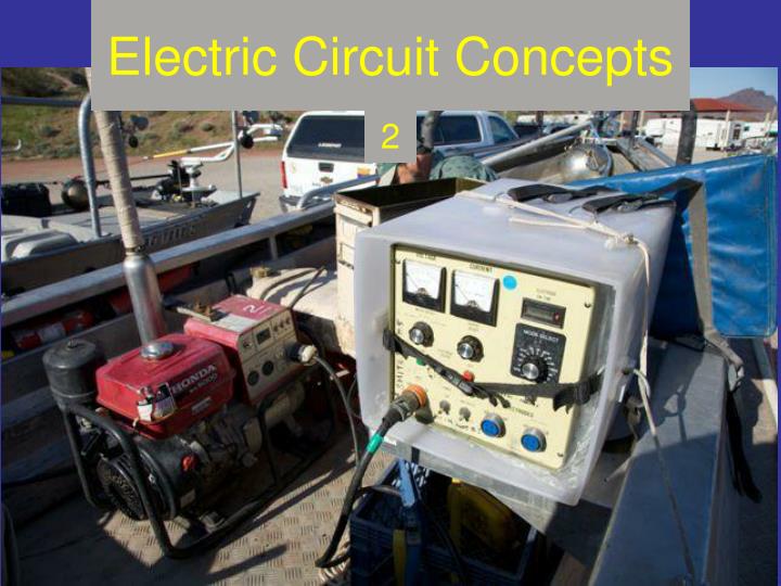
Electric Circuit Concepts. 2. Overview. Module 2: covers electricity in circuits and circuit principles The focus of Module 2 is on the equipment (except that electrode resistance calculations and design will be specifically addressed in Module 3). Session Purposes.

E N D
Overview • Module 2: covers electricity in circuits and circuit principles • The focus of Module 2 is on the equipment (except that electrode resistance calculations and design will be specifically addressed in Module 3). • .
Session Purposes • Use electric circuit principles to improve equipment design/operation and sampling. • Gain background information to engage electrode resistance and electric field concepts.
Session Objectives • Define resistance, voltage, amperage, and power • State Ohm’s Law and power equations • Draw simple circuit diagrams of electrofishing equipment (series and parallel circuits) • Calculate resistance, voltage, amperage, and power of electrofishing circuits • Describe the three principle waveforms • Draw and describe the components of a control box • State where maximum power transfer occurs and the implications for electrofishing efficiency
Session Objectives (continued) • Estimate battery discharge (and shocking) time • Check the calibration of electrofishing equipment controls and metering (include voltage, amperage, frequency, duty cycle)
To study for this section… • Work through Chapter 2 electrical principles.pdf (answers in Chapter 2 answers.pdf ) • Then review the remainder of this presentation on waveforms and equipment calibration checks • After finishing this section, go to “Electrode Characteristics” (Module 3)
Electrical Waveforms Snyder (2003)
Alternating Current Full Sine Wave 0 Volts baseline
Direct Current100% Duty Cycle 0 Volts baseline
Direct Current with Ripple100% Duty Cycle By Spinningspark The red line is continuous DC with a jagged top or “ripple”. Ripple is a result of smoothing fully rectified AC. This waveform often is used in tow-barges with DC generators. The ripple may enhance catchability and thus is sometimes exaggerated by the manufacturer. 0 Volts baseline
Pulsed DC: Half-Wave Rectified 0 Volts baseline
Pulsed DC: Full-Wave Rectified; 2x frequency 0 Volts baseline
Pulsed Direct Current: Square Wave 0 Volts baseline
Duty Cycle Video • Duty cycle is a result of two attributes, frequency and pulse width. In the following video, frequency is held constant and pulse width is varied to change duty cycle (caution: loud engine noise, make sure your speakers are turned down). • Go to: Pulse Width Adjustment
Gated Burst DC 0 Volts baseline
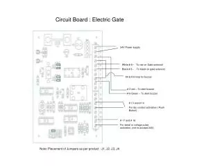
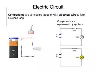
Control Box Components Battery – Direct Current Generator – Alternating Current Switch Fuse Resistor Ground
Control Box Components Gate Diode – One-way valve Silicon-Controlled Rectifier (SCR) - Thyristor Bridge Rectifier
Alternating Current + Diode = Half-Wave Rectified DC
gate Alternating Current + SCR = Controlled-Rectified DC
Changing Voltage of a PDC Waveform • The gate in the silicon-controlled rectifier allows current to flow when a set voltage is present. An SCR is a way of changing voltage on a pulsed DC waveform. The issue with this method of changing voltage is that pulse width and duty cycle vary as well. In other words, the control for voltage and the control for duty cycle are not independent. For a video example, go to: Voltage (and Pulse Width, Duty Cycle) Adjustment with SCR • An approach that keeps voltage and duty cycle controls separate or independent is inverting DC to AC, using a transformer to change voltage, and then converting (rectifying) AC back to DC. For a video example, go to: Voltage Adjustment with a Transformer
Alternating Current + Bridge Rectifier = Full-Wave Rectified DC
Example of Components Comprising an Electrofishing System (battery or generator powered) DC AC AC Battery DC-AC Inverter Transformer (change voltage) Square-wave PDC output AC Generator AC Pulser (high powered switching transistor) AC output PDC DC AC Smoothing with reservoir capacitors AC-DC Converter (rectification) DC (smooth or ripple) output Rectified PDC output
Power Source • The power source to run a control box is either a battery or a generator • Battery: go to the Battery Shocking Time Estimator tool; that Excel file will assist you in determining shocking times for lithium and lead-acid batteries under a variety of electrofishing conditions • Generator: go to the Generator Loading tool; this file will estimate power and current demand on your generator given a set of electrofishing conditions
Backpack Output Performance • Estimate of Backpack Shutdown is a teaching tool to explore the effects of maximum output average power (a design specification), duty cycle, and electrode resistance on power demand and shutoff points of backpack units.
Calibration Check Exercise for Voltage, Current, Duty Cycle, and Frequency Control Settings and Metering Fluke 199C Oscilloscope Test Setup
Equipment Checks • Calibration of meters or dials • voltage (peak, average, RMS) • current (peak, average, RMS) • duty cycle, pulse width, pulse frequency • other waveform characteristics (spikes, ripple, negative excursions) • Multimeters (especially volt-ohm) • read AC and DC; might give average PDC (Fluke 87V reads peak voltage/current for PDC waveforms • Oscilloscopes • Read out peak values for AC, DC, PDC as well as waveform shape
How to Make Measurements • See Making Voltage and Current Measurements.pdf and view a video on the field use of a current clamp: Current Clamp Use on a Backpack Shocker
A Check of Waveform Shape Pulsed Direct Current - PDC
A Check of Peak Voltage Output Peak Voltage (Vp) – 103 Volts
Another Check of Peak Voltage Output Vp – 52 Volts
Calibration Check Graph (for Peak Voltage) • It is a good idea to test a series of voltage settings from low to high at each water conductivity. The results can be compared to outputs expected using “Boat Power” or “Backpack Power” Excel tools to potentially explain output deviations from expected. Relationship between voltage setting and actual output important for voltage goal setting.
Meter Calibration Check for Peak Current • The same process can be followed to check control box current meter readings and actual amperage output (remember, there is no “current setting dial”, only a voltage dial). • A current clamp is recommended so that the main conductor does not have to be spliced into. The current clamp should be enable the reading of AC and PDC. One clamp meter on the market that has this capacity is the Fluke 80i-110s AC/DC current clamp (must be used in conjunction with a multimeter or an oscilloscope).
A Check of Pulse Width and Duty Cycle Pulse Width (PW) – 5 ms
A Check of Pulse Width and Duty Cycle Time Period (T) – 20 ms
Duty Cycle = PW ÷ Texpressed in percentDuty Cycle = 5ms ÷ 20ms = 25%
Calibration Check Graph (for Duty Cycle) Multimeter was a Fluke 87 V
A Check of Frequency T = 16.40 ms
Calibration Check Graph (for Frequency) Multimeter was a Fluke 87 V
Calibration Check Examples • There are four Excel files with calibration data on backpacks, boat control boxes, and a prospective voltage meter model.
Calibration Check Examples • The Excel file Electrofishing Product Test (on-line course link name “Electrofishing Calibration Example 1”) contains information on calibration checks of volt meters and ammeters (one backpack model and one boat control box model). In addition, a check is performed on a commercially available multimeter/clamp ammeter. This last investigation is performed to ascertain if less-expensive equipment could be used to monitor electrofishing unit outputs. • Note that the final tab on the right contains data collected in regards to voltage gradient probes and metering. This topic will be taken up later with discussions on electric fields.
Calibration Check Examples • Also check out these additional calibration examples: • Electrofishing Calibration Example 2 (boat control boxes) • Electrofishing Calibration Example 3 Low Conductivity (backpack tested under low water conductivity) • Electrofishing Calibration Example 4 High Conductivity (backpack tested under high water conductivity)
Calibration Check Video • For a calibration demonstration, you may view the instructional video at Backpack Calibration
Next Step “Electrode Characteristics” (Module 3)