Download
1 / 35
460 likes | 898 Views
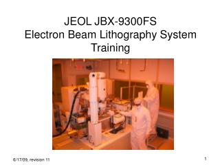
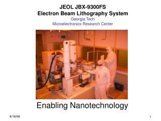
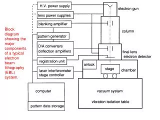
Nanoelectronics Fabrication Facility. Workshop for Electron Beam Lithography System JBX-6300FS By Nelson LI 13 November 2009. Page 1. System specifications Importance of chip feature on writing result Requirements of overlay writing Photoresist provide Requirements of pattern design

E N D
Nanoelectronics Fabrication Facility Workshop for Electron Beam Lithography SystemJBX-6300FSBy Nelson LI13 November 2009 Page 1
System specifications Importance of chip feature on writing result Requirements of overlay writing Photoresist provide Requirements of pattern design Exposure result Charging scheme Page 2
System specifications • System model • Basic specifications • Substrates supported by system Page 3
System specifications Manufacturer : JEOL Model No : JBX-6300FS SYSTEM MODEL Page 4
System specification BASIC SPECIFICATIONS Page 5
System specifications SUBSTRATES SUPPORTED BY SYSTEM Page 6
Importance of chip feature on writing result • Cassette to mount chip • Cases of improper chip feature • i, chip with rough edge • ii, chip with incorrect size • Requirements of chip feature Page 7
Importance of chip feature on writing result Back of cassette Front of cassette (writing side) Exposure window Grounding pins Chip backside Positioning pins Chip surface with PR Cassette to mount chip: Picture of cassette Page 8
Cases of improper chip feature Cassette back Cassette front (writing side) Problem: i, Grounding pin cannot touch on sample surface ii, May cause rotation error Chip with rough edges Page 9
Cases of improper chip feature Cassette back (for 15mm x15mm) chip) Cassette front (writing side) 18mm x 18mm chip Exposure window Exposure window Chip center Exposure window center Problem: Exposure area shift from center of chip Chip with incorrect size Page 10
Importance of chip feature on writing result • Straight and smooth cutting edge • Square shape with orthogonal angles • For overlay writing, patterns of • previous layer should be located at the center • of chip Requirements of chip feature Page 11
Requirements of overlay writing • Feature of Global and Chip alignment marks • Positions of Global and Chip alignment marks Page 12
Requirements of overlay writing Global Mark: L= 1500 μm W = 3 μm Chip Mark: L= 20 μm W = 3 μm Etch depth of Mark: ≧1 μm L W Feature of Global and Chip alignment marks Page 13
Requirements of overlay writing • For 4” wafer, L≦40.5mm • For 2” wafer, L≦19mm L Wafer Positions of Global alignment marks on wafer Page 14
Requirements of overlay writing Four chip alignment marks located at 4 corners of writing chip M1, M2, M3 and M4 respectively. Positions of Chip alignment marks on wafer Page 15
Photoresist Provide • Positive photoresist • i, ZEP-520A • (thickness ~400 to 100nm) • ii, ZEP-7000 • (for mask, thickness ~400 to 150nm) • iii, PMMA950-A2 (thickness ~180 to 80nm) • Negative photoresist • i, AR-N7520.18 (thickness ~400nm) • ii, AR-N7520.073 (thickness ~100nm) Page 16
Requirements of pattern design • File format, pattern sizes and pattern area • Pattern samples Page 17
Requirements of pattern • File format: GDSII • Total number of vertex point per polygon ≦600 • Pattern sizes(line width or gap size) ≧ 100nm • Pattern Complexity ↑, file conversion time ↑ Pattern sizes and file format Page 18
Requirements of pattern • Problems of larger exposure area • i, long writing time • ii, high risk of field stitching error due to laboratory temperature fluctuation Stitching error Pattern sizes and file format Page 19
Requirements of pattern iii, Proximity error Correct expose 100 μm 120 μm Over expose Pattern sizes and file format Page 19
Requirements of pattern 1500 μm Chip area: 1500um2 Exposure area: 11.51% of Chip area Exposure time: 10.4mins 1500 μm Pattern sample 1 Page 20
Requirements of pattern 500 μm 0.2 μm line width 500 μm Chip area: 500um2 Exposure area: 11.51% of Chip area Exposure time: 1min Pattern sample 2 Page 21
Requirements of pattern 500 μm 100 μm 0.1 μm x 0.2 μm polygon 500 μm Pattern conversion fail! Pattern sample 3 Page 22
Exposure result • Pattern sample 1 • Pattern sample 2 Page 23
Exposure result 80nm line width 100nm line width ZEP-520A (+) ma-N2403 (-) Pattern sample 1: Shot bar pattern Page 24
Exposure result 100nm line width 100nm2 square pattern ZEP-520A (+) ma-N2403 (-) Pattern sample 1 Page 25
Exposure result Zigzag patterns with 100nm line width 50nm line patterns with 0.3 ° rotation angle ZEP-520A (+) Pattern sample 1 Page 26
Exposure result ZEP-520A (+) ma-N2403 (-) Pattern sample 2 Page 27
Charging Scheme • Definitions of Short and Long jobs • Charging for internal users • Charging for other HK Institutions • Charging for external users • Job submission procedure Page 28
Charging Scheme • Short job: Exposure time ≦3hrs • Long job: Exposure time ﹥3hrs Charging Scheme: Definition of Short and Long jobs Page 29
Charging Scheme Charging Scheme: Charging for internal users Page 30
Charging Scheme Remark: Price includes 16% administration fee Charging Scheme: Charging for external users and other HK Institutions Page 31
Charging Scheme The price list of substrates will post on website on coming Monday! Job submission procedure: internal users Page 32
Charging Scheme Go to www.nff.ust.hk 2. 3. 4. Job submission procedure: for external users and other HK Institutions Page33
Nanoelectronics Fabrication Facility Thankyou Contact Information : Name: Nelson LI Email : eenelson@ust.hk Job submission procedure Page 34