Download
1 / 23
230 likes | 461 Views
ATM 기반의 IP Overlay 모델 분석. 2000. 4. 19. 통신망연구소 한국통신. 목 차. IP Service Model over ATM Networks Overlay Model Modeling Numerical Result & Discussions. IP Service Models. IP/ATM Service Model. Overlay Model Overlay of ATM/IP address and routing LAN Emulation IP over ATM (IPOA)

E N D
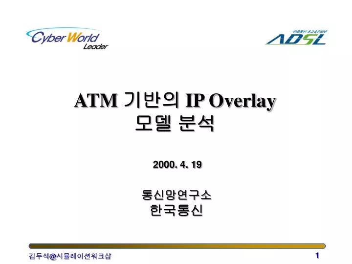
ATM 기반의 IP Overlay 모델 분석 2000. 4. 19 통신망연구소 한국통신
목 차 • IP Service Model over ATM Networks • Overlay Model Modeling • Numerical Result & Discussions
IP/ATM Service Model • Overlay Model • Overlay of ATM/IP address and routing • LAN Emulation • IP over ATM (IPOA) • Multi Protocol over ATM (MPOA) • Integrated Model • Integration of ATM/IP addressing and routing • MPLS (Multi Protocol Label Switching) • IP Switching, Tag Switching, CSR, ARIS • I-PNNI, PAR
R R ARS3 ARS1 ARS2 ARP over ATM • Address Resolution Protocol • LIS server (ATMARP server) responds to ARP • The outcome of “Local/Remote” decision is based only on the address information LIS2 LIS1 LIS3 ATM Network R : Router ARS : ATMARP Server
ELAN, MPS 1 MPS 2 LIS, etc. ELAN ELAN MPC 1 MPC 2 Data Transfer Flow in MPOA • Default Path • Shortcut Path Default Path Default Path Default Path Shortcut
NHS2 NHS3 NHS1 NH- NHS4 reply NH- requests NH- ATM Network requests LIS1 LIS2 LIS3 LIS4 NH- reply Direct Connection ATM host B ATM host A NHRP Operation (typical) Serving NHS
Router Router Router Router Router Router Classical IPOA Connection LIS0 (L2) LIS3 (L1) LIS1 (L1) ATM Network LIS2 (L1) LIS4 (L1)
LIS0 (L2) LIS3 (L1) LIS1 (L1) Router Router ATM Network Router LIS2 (L1) Router LIS4 (L1) Router Router NHRP/MPOA Connection No. of Connection - O(n2)
Overlay Model Analysis • Survey on Classical IPOA Model Analysis • Virtual circuit holding time • SVC-based • Delayed Vacation Model • Performance Measures • VCC setup rate • VC utilization • average delay
Level 3 Net1 Level 2 Net1.1 Net1.2 Net1.1.1 Level 1 Net1.2.2 Subnet 1.1.2 Subnet 1.1.1.1 Subnet 1.1.1.2 Net1.2.1 Internet Hierarchy -Example
Level 3 NHS1 NHS2 Level 2 NHS1.1 NHS1.2 NHS2.1 NHS2.2 Level 1 NHS2.2.2 NHS1.1.2 NHS2.2.1 NHS1.1.1 NBMA subnet 1.2 NBMA subnet 2.2.1 NBMA subnet 2.2.2 NBMA subnet 1.1.1 NBMA subnet 1.1.2 MPOA/NHRP Hierarchy
State Transition Diagram Customer arrives if open VCC exist Idle (I) Customer arrives if open VCC does not exist Setup (S) Channel Close (C) No customers arrived during open interval Setup complete Serving (B) Open (O) Queue empty Customer arrives during V
Analysis Model • ATM SVC-based NBMA • Serving NHS만 응답 • Authority bit = 1 로 설정된 경우만 고려 • Connection State 관리와 Address cache • Soft-state connection 관리 • Address resolution 결과 cache • cache entry가 timeout과 connection release 관계 • cache timeout과 channel timeout을 동일한 것으로 가정 • 분석 모델 • 모델 I : 주소 캐쉬를 사용하지 않는 경우 • 모델 II : 주소 캐쉬를 사용하며 캐쉬 시간 만료가 없는 경우 • 모델 III : 주소 캐쉬를 사용하며 캐쉬 시간 만료가 있는 경우
Scalability Analysis Measures • Control Processing Aspect • Singnalling processing capacity • ARP processing capacity • Response time • Resource Management Aspect • Number of channels • Resource Utilization • Cache/Routing table size
Assumptions • NBMA 망 구성 • 총 512 클라이언트 노드 • 3 계위 계층화 • 64개 노드 단위로 8개의 서브망으로 분할 • ARP 응답 평균 홉 수 • NBMA 서브망 1을 기준으로 볼 때 NBMA 서브망j (j=1, 2, ... , 8)로의 NHRP 홉 수는 {1, 2, 3, 3, 4, 4, 4, 4} • Flow Duration • Geometric distribution • Uniform distribution • Destination 분포 • Uniform distribution
1.E+01 1.E-01 No cache T=2min Hops T=1min 1.E-03 Average Response T=5min 1.E-05 0.1 0.3 0.5 0.7 0.9 Arrival Traffic Rate Average Response Hop • Cache timeout & Hit ratio 관계 • Cache timeout (CT)가 2분 이상인 경우 응답 홉 수가 크게 줄어듬 • 트래픽 양이 많을수록 평균 응답 홉 수가 줄어듬
Channel Utilization • CT와 open VCC 간의 관계 • CT가 클수록 채널 사용률이 떨어짐 • CT가 5분 이상일 경우 하나의 노드에서 개방한 채널의 개수가 전체 노드 수에 육박 (O(n2))
Average # of Open Channels • Network Resource & Control Processing trade-off • CT가 클수록 채널 사용률이 떨어짐 • CT가 5분 이상일 경우 하나의 노드에서 개방한 채널의 개수가 전체 노드 수에 육박 (O(n2))
Signalling Load Effect • Signalling Load 분석 • CT = 1, 5 min. • CT가 작을수록 시그널링 부하가 커짐 • Network Resource & Control Processing trade-off
Conclusions • 처리 부하와 망 자원간 trade-off • 캐쉬 만료 값을 크게 할 수록 NHRP 질의 및 시그널링 등 망 장치의 처리 부하 (processing load)가 줄어듬 • 소요 채널 수가 늘어 나고 채널 사용율이 떨어지는 등 망의 자원 소모량은 크게 남 • 초고속정보통신망에서 NHRP 모델 적용 범위 • 상대적으로 트래픽 발생량이 적고 단말 수가 많은 사용자 단까지 적용하는 것은 무리 • 트래픽이 집중되는 인터넷 접속 서버, 라우터 및 주요 서비스 노드 간에 적용한다면 트래픽양이 증가하더라도 확장성을 보일 수 있음 • FFS • 좀 더 일반화된 모델 분석 • Integrated 모델과의 비교 분석