Download

1 / 20
210 likes | 421 Views
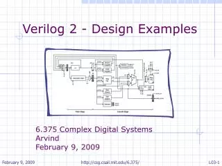
6. VHDL/Verilog Behavioral Description. Verilog for Synthesis: Behavioral description. Instead of instantiating components, describe them using behavioral description in a single module Connect the various components using internal signals Advantages: Often allows for shorter description

E N D
Verilog for Synthesis: Behavioral description • Instead of instantiating components, describe them using behavioral description in a single module • Connect the various components using internal signals • Advantages: • Often allows for shorter description • A single module may be needed to describe a project consisting of various components • Easier to understand the behavior of the internal components • Disadvantages: • It might reduce code readability – Comments here are necesarry! • Can lead to large files i.e. hundredths of lines of code
Verilog for Synthesis: Behavioral description example SSG Decoder again: module Ssg_decoder #( parameter CLK_FREQ = 50000000, parameter REFRESH_RATE = 1000) (input CLK, input RESET, input [15:0] DIN, output [3:0] AN, output [6:0] SSG); //now we need more internal signals //to make the frequency divider wire CE; integer Freq_divider; //to make the shift register reg [3:0] AN_Int; //to make the multiplexer wire [3:0] mux_data; //mux_addr disappeard! The priority //decoder will be also made using behavioral // description //to make the Hex_to_ssg_decoder reg [6:0] SSG_Int; #(CLK_FREQREFRESH_RATE) #(CLK_FREQREFRESH_RATE) #(CLK_FREQREFRESH_RATE) Ssg_decoder Ssg_decoder Freq_divider CLK CLK #(CLK_FREQ, DIV_RATE) #(CLK_FREQ, DIV_RATE) CLK CE_div CE CE Shift_reg_walk_0 AN CLK AN RESET RESET AN RESET 4 4 4 AN_Int CE AN_Int Priority_decoder Din Dout 2 4 mux_addr mux_addr Din[3:0] 2 Mux_4X_4To1 I0 4 [7:4] Din Din mux_data I1 mux_data O Hex_to_ssg_encoder 4 SSG I2 16 16 4 SSG 4 [11:8] Din Dout A I3 7 7 4 [15:11] 7 4
Verilog for Synthesis: Behavioral description example SSG Decoder again: //describe the divider always @ (posedge CLK) if (Freq_divider == ((CLK_FREQUENCY_HZ/REFRESH_RATE) - 1 )) Freq_divider <=0; else Freq_divider <= Freq_divider + 1; //assign the divided signal assign CE = (CE_div == ((CLK_FREQUENCY_HZ/REFRESH_RATE) - 1 )) ? 1:0; //note: CE is one-shot signal! //describe the walking 0 shift register always @ (posedge CLK or posedge RESET) if (RESET) AN_Int<=4'hf; elseif (CE) if (AN_Int==4'b0111 || AN_Int==4'b0000 || AN_Int==4'b1111) AN_Int<=4'b1110; else AN_Int <= {AN_Int[2:0],1'b1}; //shift register #(CLK_FREQREFRESH_RATE) #(CLK_FREQREFRESH_RATE) #(CLK_FREQREFRESH_RATE) Ssg_decoder Ssg_decoder Freq_divider CLK CLK #(CLK_FREQ, DIV_RATE) #(CLK_FREQ, DIV_RATE) CLK CE_div CE CE Shift_reg_walk_0 AN CLK AN RESET RESET AN RESET 4 4 4 AN_Int CE AN_Int Priority_decoder Din Dout 2 4 mux_addr mux_addr Din[3:0] 2 Mux_4X_4To1 I0 4 [7:4] Din Din mux_data I1 mux_data O Hex_to_ssg_encoder 4 SSG I2 16 16 4 SSG 4 [11:8] Din Dout A I3 7 7 4 [15:11] 7 4
Verilog for Synthesis: Behavioral description example SSG Decoder again: //Priority encoder and multiplexer combined assign mux_data = (An_Int==4'b1110) ? DIN[3:0] : (An_Int==4'b1101) ? DIN[7:4] : (An_Int==4'b1011) ? DIN[11:8] : (An_Int==4'b0111) ? DIN[15:12] : 4'h0; #(CLK_FREQREFRESH_RATE) #(CLK_FREQREFRESH_RATE) #(CLK_FREQREFRESH_RATE) Ssg_decoder Ssg_decoder Freq_divider CLK CLK #(CLK_FREQ, DIV_RATE) #(CLK_FREQ, DIV_RATE) CLK CE_div CE CE Shift_reg_walk_0 AN CLK AN RESET RESET AN RESET 4 4 4 AN_Int CE AN_Int Priority_decoder Din Dout 2 4 mux_addr mux_addr Din[3:0] 2 Mux_4X_4To1 I0 4 [7:4] Din Din mux_data I1 mux_data O Hex_to_ssg_encoder 4 SSG I2 16 16 4 SSG 4 [11:8] Din Dout A I3 7 7 4 [15:11] 7 4
Verilog for Synthesis: Behavioral description example SSG Decoder again: //write the seven segment decoder always @ (mux_data) case (mux_data) 4'b0001: Ssg_Int=7'b1111001; //1 4'b0010: Ssg_Int=7'b0100100; //2 4'b0011: Ssg_Int=7'b0110000; //3 4'b0100: Ssg_Int=7'b0011001; //4 4'b0101: Ssg_Int=7'b0010010; //5 4'b0110: Ssg_Int=7'b0000010; //6 4'b0111: Ssg_Int=7'b1111000; //7 4'b1000: Ssg_Int=7'b0000000; //8 4'b1001: Ssg_Int=7'b0010000; //9 4'b1010: Ssg_Int=7'b0001000; //A 4'b1011: Ssg_Int=7'b0000011; //B 4'b1100: Ssg_Int=7'b1000110; //C 4'b1101: Ssg_Int=7'b0100001; //D 4'b1110: Ssg_Int=7'b0000110; //E 4'b1111: Ssg_Int=7'b0001110; //F default: Ssg_Int=7'b1000000; //0 endcase #(CLK_FREQREFRESH_RATE) #(CLK_FREQREFRESH_RATE) #(CLK_FREQREFRESH_RATE) Ssg_decoder Ssg_decoder Freq_divider CLK CLK #(CLK_FREQ, DIV_RATE) #(CLK_FREQ, DIV_RATE) CLK CE_div CE CE Shift_reg_walk_0 AN CLK AN RESET RESET AN RESET 4 4 4 AN_Int CE AN_Int Priority_decoder Din Dout 2 4 mux_addr mux_addr Din[3:0] 2 Mux_4X_4To1 I0 4 [7:4] Din Din mux_data I1 mux_data O Hex_to_ssg_encoder 4 SSG I2 16 16 4 SSG 4 [11:8] Din Dout A I3 7 7 4 [15:11] 7 4
Verilog for Synthesis: Behavioral description example SSG Decoder again: //Do NOT forget to assign the outputs! //Otherwise, the module will be REMOVED //by the synthesizer assign AN = AN_Int; assign SSG = SSG_Int; // Suggestion 1: better make the output //assignment at the beginning of the file! //Suggestion 2: for each component to be made, //write its comment first, then fill the code //with instructions! Such as: //Here comes the frequency divider //Here comes the shift register //… endmodule #(CLK_FREQREFRESH_RATE) #(CLK_FREQREFRESH_RATE) #(CLK_FREQREFRESH_RATE) Ssg_decoder Ssg_decoder Freq_divider CLK CLK #(CLK_FREQ, DIV_RATE) #(CLK_FREQ, DIV_RATE) CLK CE_div CE CE Shift_reg_walk_0 AN CLK AN RESET RESET AN RESET 4 4 4 AN_Int CE AN_Int Priority_decoder Din Dout 2 4 mux_addr mux_addr Din[3:0] 2 Mux_4X_4To1 I0 4 [7:4] Din Din mux_data I1 mux_data O Hex_to_ssg_encoder 4 SSG I2 16 16 4 SSG 4 [11:8] Din Dout A I3 7 7 4 [15:11] 7 4
Verilog for Synthesis: Behavioral description example SSG Decoder again: //Do NOT forget to assign the outputs! //Otherwise, the module will be REMOVED //by the synthesizer assign AN = AN_Int; assign SSG = SSG_Int; // Suggestion 1: better make the output //assignment at the beginning of the file! //Suggestion 2: for each component to be made, //write its comment first, then fill the code //with instructions! Such as: //Here comes the frequency divider //Here comes the shift register //… endmodule #(CLK_FREQREFRESH_RATE) #(CLK_FREQREFRESH_RATE) #(CLK_FREQREFRESH_RATE) Ssg_decoder Ssg_decoder Freq_divider CLK CLK #(CLK_FREQ, DIV_RATE) #(CLK_FREQ, DIV_RATE) CLK CE_div CE CE Shift_reg_walk_0 AN CLK AN RESET RESET AN RESET 4 4 4 AN_Int CE AN_Int Priority_decoder Din Dout 2 4 mux_addr mux_addr Din[3:0] 2 Mux_4X_4To1 I0 4 [7:4] Din Din mux_data I1 mux_data O Hex_to_ssg_encoder 4 SSG I2 16 16 4 SSG 4 [11:8] Din Dout A I3 7 7 4 [15:11] 7 4
Verilog for Synthesis: Behavioral description • Q: Which one should I use: Behavioral or Hierarchical description? • A: It depends... • Create modules that can be REUSED. Those later can be used as hierarchical components in other projects. Examples: • Ssg_Decoder • Your components in your project need to run at several different frequencies? • Create a PARAMETRIZED divider then use it! • You can describe the divider using behavioral description, NOT as a set of counters and comparators! • Conclusion (?): Decide based on the experience you have • I.e. try both • There is a reason for the existence of project managers!
Verilog for Synthesis: Behavioral description • Q: What signals should I declare: wire or reg? • A: 1. For SEQUENTIAL components/signals (components running synchronous to a clock signal): • The answer is clearly reg (the signal has to be assigned in a always @ (posedge CLK) statement! • For COMBINATIONAL components/signals: • Use continuous (assign) assignments whenever possible (also if it worth) • You avoid in this way incomplete assignments (what are those…?) – the syntax checker will generate an error in the case of an incomplete assignment! • Combinational loops (again, what are those…?) cannot be avoided • To describe logic with many inputs and outputs such as state-machine logic or decoders/encoders, consider using always statements • There is a risk of both incomplete assignments and combinational loops
Verilog for Synthesis: Behavioral description • To describe logic with many inputs and outputs such as state-machine logic or decoders/encoders, consider using always statements • Example: the Hex_to_ssg decoder, if it would be made using continuous assignments: • assign Ssg_Int = (mux_data == 4’b0001) ? 7’b1111001 : • (mux_data == 4’b0010) ? 7’b0100100: …. • More text/symbols to write than using a case statement: • case (mux_data) • 4'b0001: Ssg_Int=7'b1111001; //1 • 4'b0010: Ssg_Int=7'b0100100; //2 • … • default: Ssg_Int=7'b1000000; //0 • endcase • Special casez or casex statements in Verilog: casez: treat ‘z’ as don’t care, casex: treat ‘z’ and ‘x’ as don’t care • Used mostly in simulation (testbenches)
Verilog for Synthesis: Sequential always statements • Example: • always @ (posedge CLK or posedge Reset or posedge Load) • if (Reset) cnt <= 0; • elseif (Load) cnt <= Din; • elseif (CE) cnt <= cnt +1; • CLK will be the CLOCK signal NOT BECAUSE IS CALLED CLK! • Because is the signal that is not present as a CONDITION in the code! • Remember that the clock signal is the one that gives the RHYTHM of a synchronous circuit! (as a cowbell for cows or drum for music) • Also, Reset is the reset signal, Load is the load signal, Reset has HIGHER PRIORITY, BOTH ARE ACTIVE_HIGH and BOTH ARE ASYNCHRONOUS because: • The (Reset) condition causes cnt <= 0. (Reset) is equivalent to (Reset == 1’b1) (Reset is a reset signal) • The (Load) condition causes cnt <= Din (Load is a load signal) • Reset is checked BEFORE Load! (Reset has higher priority) • BOTH signals are in the sensitivity list as posedge, also checked against 1 (Both are asynchronous and active-high) • … Not because the reset signal is called Reset and …
Verilog for Synthesis: Sequential always statements • Example: • always @ (posedge CLK or posedge Reset or posedge Load) • if (Reset) cnt <= 0; • elseif (Load) cnt <= Din; • elseif (CE) cnt <= cnt +1; • CE is a Clock Enable signal and is SYNCHRONOUS • Because enables counting • Because CE DOES NOT APPEAR IN THE SENSITIVITY LIST • The asynchronous signals have always HIGHER priority than the synchronous signals • Then the asynchronous signals have to be tested FIRST! • Example (BAD): • always @ (posedge CLK or posedge Reset or posedge Load) • if (CE) cnt <= cnt +1; • else if (Reset) cnt <= Din; • ..
Verilog for Synthesis: Sequential always statements • Example: • always @ (posedge CLK or posedge Reset or posedge Load) • if (Reset) cnt <= 0; • elseif (Load) cnt <= Din; • elseif (CE) cnt <= cnt +1; • The asynchronous signals have always HIGHER priority than the synchronous signals • Then the asynchronous signals have to be tested FIRST! • Example (BAD): • always @ (posedge CLK or posedge Reset or posedge Load) • if (CE) cnt <= cnt +1; • else if (Reset) cnt <= Din; • Example (GOOD!) • always @ (posedge CLK or posedge Reset or posedge Load) begin • if (CE) cnt <= cnt +1; • if (Load) cnt <= Din; • if (Reset) cnt <= 0; • The last change (if the condition is true) is cnt <= 0;. Therefore Reset has the highest priority! • Not recommended. Some synthesizers may not recognize the counter
Verilog for Synthesis: Sequential always statements • Example: • always @ (posedge CLK or posedge Reset or posedge Load) • if (Reset) cnt <= 0; • elseif (Load) cnt <= Din; • elseif (CE) cnt <= cnt +1; • The posedge or negedge statements have to be in conjunction with the condition tested • Otherwise the synthesizer generates an error • Examples (BAD): • always @ (posedge CLK or posedge Reset or posedge Load) • if (!Reset) cnt <= cnt +1; • else if (Reset) cnt <= Din; • … • always @ (posedge CLK or negedge Reset or posedge Load) • if (CE) cnt <= cnt +1; • else if (Reset) cnt <= Din; • …
Verilog for Synthesis: Sequential always statements • Avoid describing combinational logic for asynchronous control signals! • Example (BAD): • always @ (posedge CLK or posedge Reset1 or posedge Reset2) • if (Reset1 || Reset2) cnt <= 0; • else if (Load) cnt <= Din; • else if (CE) cnt <= cnt +1; • ISE 12.2 may accept it, ISE 12.3 or 13.X might not! (calling XST in batch mode from EDK, for example) • Reason: it may “believe” that we want to syntesize a sequential circuit with two reset signals! • Example (correct) • wire Reset = Reset1 | Reset2; • always @ (posedge CLK or posedge Reset) • if (Reset) cnt <= 0; • …
Verilog for Synthesis: Sequential always statements • Avoid using the SAME priority for asynchronous and synchronous control signals! • Example (BAD): • always @ (posedge CLK or posedge Reset1) • if (Reset1 || Reset2 || Reset3) cnt <= 0; • else if (Load) cnt <= Din; • else if (CE) cnt <= cnt +1; • Reset1 is asynchronous, but Reset2 and Reset3 are synchronous! • Have you seen a flip-flop with both synchronous and asynchronous reset, also with synchronous load? • It is possible to make it. How? • Then describe the circuit so! • Example (correct): Make all of the reset signals either synchronous or asynchronous • wire Reset = Reset1 | Reset2 | Reset3; • always @ (posedge CLK or posedge Reset) • if (Reset) cnt <= 0; … • Or: • wire Reset = Reset1 | Reset2 | Reset3; • always @ (posedge CLK) …
Verilog for Synthesis: Combinational always statements • Generates COMBINATIONAL CIRCUITS • Example: • always @ (A or B or C) • if (A) D <= 1; • elseif (B||C) D <=1; • else D <= 0; • What circuit will be generated by the synthesizer? • Note: for combinational always statements, both changes (from 0 to 1 or from 1 to 0 matter) – combinational circuits may change their output when the input changes, regardless of a clock signal • Do not use posedge or negedge conditions for combinational always statements! It may either: • Make a sequential circuit, if there is an extra signal in the sensitivity list, or • Synthesizer generates an error
Verilog for Synthesis: Combinational always statements • Generates COMBINATIONAL CIRCUITS • All the signals read inside the always statements should be on the sensitivity list, otherwise simulation differences appear between behavioral and post-translate! • Reason: • The syntesizer IGNORES the sensitivity list and will connect signals read inside the always statement, only generates a warning • The simulator WILL NOT run the always statement when a signal changes, if the signal is not on the sensitivity list! • Conclusion: DO NOT make exclusions based on the sensitivity list!
Verilog for Synthesis: Combinational always statements • Combinational always statements: include decision-based statements: if..else, case..endcase • Every if has to have an else branch! Every case has to contain every branch (default, if not) • Otherwise: we have incomplete assignments that lead to latch inference! • SO: What to avoid in combinational always statements?