Download

1 / 386
4.87k likes | 6.27k Views
Understanding Magnetic Flux Leakage Testing Reading 1

E N D
Understanding Magnetic Flux Leakage R eading 1 My ASNT Level III Pre-Exam Study Note 30th August 2015 Charlie Chong/ Fion Zhang
Permafrost Zone Pipeline MFLT Charlie Chong/ Fion Zhang
Offshore Pipeline MFLT Charlie Chong/ Fion Zhang
Cross Country Pipeline MFLT Charlie Chong/ Fion Zhang
Offshore Pipeline MFLT Charlie Chong/ Fion Zhang
Cross Country Pipeline MFLT Charlie Chong/ Fion Zhang
Cross Country Pipeline MFLT Charlie Chong/ Fion Zhang
Offshore Pipeline MFLT Charlie Chong/ Fion Zhang
Tank Bottom MFLT Charlie Chong/ Fion Zhang
Tank Bottom MFLT Charlie Chong/ Fion Zhang
Tank Bottom MFLT Charlie Chong/ Fion Zhang
Wire Rope MFLT Charlie Chong/ Fion Zhang
Drilling String MFLT Charlie Chong/ Fion Zhang
Reading I Content Reading One: E1571 (Revisiting) Reading Two: Magnetic Flux and SLOFEC Inspection of Thick Walled Components (Revisited) Reading Three: Reading Four: Charlie Chong/ Fion Zhang
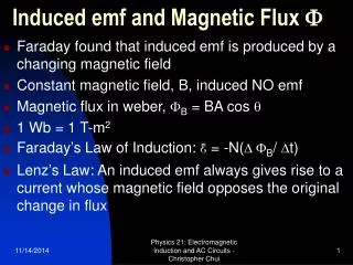
Principle of MFL Testing MFL testing is a magnetic based NDT method. The method is used to detect corrosion and cracks in ferromagnetic materials, such as pipelines, storage tanks, ropes and cables [10,27–29]. The basic principle of MFL testing is that the flux lines pass through the steel wires when a magnetic field is applied to the cable. At areas where corrosion or missing metal exists, the magnetic- field leaks from the wires. In an MFL tool, magnetic sensors are placed between the poles of the magnet to detect the leakage field. The signal of the leakage field is analyzed to identify the damaged areas and estimate the amount of metal loss. Thus, the transducer includes magnetizers and magnetic sensors. The magnetic-field can be produced by a permanent magnet yoke, or a solenoid with the direct current. The magnetic-field density needs to meet near saturation under the sensor. Figure 3 shows the principle of MFL testing. The permanent magnet yoke is used to produce the magnetic-field, and the coil is used to induce (detect?) the leakage field. Charlie Chong/ Fion Zhang
Figure 3. Principle of MFL testing. (a) Undamaged cable; (b) Cable with metal loss. Charlie Chong/ Fion Zhang
R eading 1 E1571 Standard Practice for Electromagnetic Examination of Ferromagnetic Steel W ire R ope Charlie Chong/ Fion Zhang
1. Scope 1.1 This practice covers the application and standardization of instruments that use the electromagnetic, the magnetic flux, and the magnetic flux leakage examination method to detect flaws and changes in metallic cross- ectional areas in ferromagnetic wire rope products. 1.1.1 This practice includes rope diameters up to 2.5 in. (63.5 mm). Larger diameters may be included, subject to agreement by the users of this practice. 1.2 This standard does not purport to address all of the safety concerns, if any, associated with its use. It is the responsibility of the user of this standard to establish appropriate safety and health practices and determine the applicability of regulatory limitations prior to use. Charlie Chong/ Fion Zhang
2. Referenced Documents 2.1 ASTM Standards: E 543 Practice for Agencies Performing Nondestructive Testing E 1316 Terminology for Nondestructive Examinations2 Charlie Chong/ Fion Zhang
3. Terminology 3.1 Definitions—See Terminology E 1316 for general terminology applicable to this practice. 3.2 Definitions of Terms Specific to This Standard: 3.2.1 dual- unction instrument—a wire rope NDT instrument designed to detect and display changes of metallic cross-sectional area on one channel and local flaws on another channel of a dual-channel strip chart recorder or another appropriate device. 3.2.2 local flaw (LF)—a discontinuity in a rope, such as a broken or damaged wire, a corrosion pit on a wire, a groove worn into a wire, or any other physical condition that degrades the integrity of the rope in a localized manner. 3.2.3 loss of metallic cross-sectional area (LMA)—a relative measure of the amount of material (mass) missing from a location along the wire rope and is measured by comparing a point with a reference point on the rope that represents maximum metallic cross-sectional area, as measured with an instrument. Charlie Chong/ Fion Zhang
3.2.4 single-function instrument—a wire rope NDT instrument designed to detect and display either changes in metallic cross-sectional area or local flaws, but not both, on a strip chart recorder or another appropriate device. Keywords: changes in metallic cross-sectional area local flaws Charlie Chong/ Fion Zhang
4. Summary of Practice 4.1 The principle of operation of a wire rope nondestructive examination instrument is as follows: 4.1.1 AC Electromagnetic Instrument—An electromagnetic wire rope examination instrument works on the transformer principle with primary and secondary coils wound around the rope (Fig. 1). The rope acts as the transformer core. The primary (exciter) coil is energized with a low frequency alternating current (ac), typically in the 10 to 30 Hz range. The secondary (search) coil measures the magnetic characteristics of the rope. Any significant change in the magnetic characteristics in the core (wire rope) will be reflected as voltage changes (amplitude and phase) in the secondary coil. Electromagnetic instruments operate at relatively low magnetic field strengths; therefore, it is necessary to completely demagnetize the rope before the start of an examination. This type of instrument is designed to detect changes in metallic crosssectional area. Charlie Chong/ Fion Zhang
Keywords: AC- Alternating Current System Electromagnetic instruments operate at relatively low magnetic field strengths; it is necessary to completely demagnetize the rope before the start of an examination. This type of instrument is designed to detect changes in metallic crosssectional area. Charlie Chong/ Fion Zhang
Alternating Field MFL method The Alternating Field MFL probe rotates at high speed around the longitudinally moved test material and scans its surface helically. The rotating probe scans „punctiform“ only a small area of the material surface at any moment, i.e. when testing, it focuses on a very small part of the overall surface. Thus, even an extremely small material flaw represents a major disturbance with respect to this relatively small material surface area. One other advantage of the rotating probe method: Long drawn-out material flaws are indicated over their full length. Charlie Chong/ Fion Zhang MAGNETIC FLUX LEAKAGE TESTING WITH CIRCOFLUX®
Alternating Field MFL method Charlie Chong/ Fion Zhang MAGNETIC FLUX LEAKAGE TESTING WITH CIRCOFLUX®
Alternating Field MFL method Charlie Chong/ Fion Zhang MAGNETIC FLUX LEAKAGE TESTING WITH CIRCOFLUX®
FIG. 1 Schematic Representation of an Electromagnetic Instrument Sensor- Head Charlie Chong/ Fion Zhang
4.1.2 Direct Current and Permanent Magnet (Magnetic Flux) Instruments- Direct current (dc) and permanent magnet instruments (Figs. 2 and 3) supply a constant flux that magnetizes a length of rope as it passes through the sensor head (magnetizing circuit). The total axial magnetic flux in the rope can be measured either by Hall effect sensors, an encircling (sense) coil, or by any other appropriate device that can measure absolute magnetic fields or variations in a steady magnetic field. The signal from the sensors is electronically processed, and the output voltage is proportional to the volume of steel or the change in metallic cross-sectional area, within the region of influence of the magnetizing circuit. This type of instrument measures changes in metallic cross-sectional area. Charlie Chong/ Fion Zhang
FIG. 2 Schematic Representation of a Permanent Magnet Equipped Sensor- Head Using a Sense Coil to Measure the Loss of Metallic Cross- ectional Area Charlie Chong/ Fion Zhang
FIG. 2 Schematic Representation of a Permanent Magnet Equipped Sensor- Head Using a Sense Coil to Measure the Loss of Metallic Cross- ectional Area Sensor Head 8.1.3 The sensor head, containing the energizing and detecting units, and other components, should be designed to accommodate different rope diameters. The rope should be approximately centered in the sensor head. Charlie Chong/ Fion Zhang
FIG. 3 Schematic Representation of a Permanent Magnet Equipped Sensor- head Using Hall Devices to Measure the Loss of Metallic Cross-Sectional Area Sensor Head Hall Devices Hall Devices Charlie Chong/ Fion Zhang
4.1.3 Magnetic Flux Leakage Instrument- A direct current (DC) or permanent magnet instrument (Fig. 4) is used to supply a constant flux that magnetizes a length of rope as it passes through the sensor head (magnetizing circuit). The magnetic flux leakage created by a discontinuity in the rope, such as a broken wire, can be detected with a differential sensor, such as a Hall effect sensor, sensor coils, or by any appropriate device. The signal from the sensor is electronically processed and recorded. This type of instrument measures LFs. While the information is not quantitative as to the exact nature and magnitude of the causal flaws, valuable conclusions can be drawn as to the presence of broken wires, internal corrosion, and fretting of wires in the rope.” Charlie Chong/ Fion Zhang
4.2 The examination is conducted using one or more techniques discussed in 4.1. Loss of metallic cross-sectional area can be determined by using an instrument operating according to the principle discussed in 4.1.1 and 4.1.2. Broken wires and internal (or external) corrosion can be detected by using a magnetic flux leakage instrument as described in 4.1.3. The examination procedure must conform to Section 9. One instrument may incorporate both magnetic flux and magnetic flux leakage principles. Charlie Chong/ Fion Zhang
5. Significance and Use 5.1 This practice outlines a procedure to standardize an instrument and to use the instrument to examine ferromagnetic wire rope products in which the electromagnetic, magnetic flux, magnetic flux leakage, or any combination of these methods is used. If properly applied, the electromagnetic and the magnetic flux methods are capable of detecting the presence, location, and magnitude of metal loss from wear and corrosion, and the magnetic flux leakage method is capable of detecting the presence and location of flaws such as broken wires and corrosion pits. 5.2 The instrument’s response to the rope’s fabrication, installation, and in- service-induced flaws can be significantly different from the instrument’s response to artificial flaws such as wire gaps or added wires. For this reason, it is preferable to detect and mark (using set-up standards that represent) real in-service-induced flaws whose characteristics will adversely affect the serviceability of the wire rope. Charlie Chong/ Fion Zhang
6. Basis of Application 6.1 The following items require agreement by the users of this practice and should be included in the rope examination contract: 6.1.1 Acceptance criteria. 6.1.2 Determination of LMA, or the display of LFs, or both. 6.1.3 Extent of rope examination (that is, full length that may require several setups or partial length with one setup). 6.1.4 Standardization method to be used: wire rope reference standard, rod reference standards, or a combination thereof. 6.1.5 Maximum time interval between equipment standardizations. Charlie Chong/ Fion Zhang
6.2 Wire Rope Reference Standard (Fig. 5): 6.2.1 Type, dimension, location, and number of artificial anomalies to be placed on a wire rope reference standard. 6.2.2 Methods of verifying dimensions of artificial anomalies placed on a wire rope reference standard and allowable tolerances. 6.2.3 Diameter and construction of wire rope(s) used for a wire rope reference standard. 6.3 Rod Reference Standards (Fig. 6): 6.3.1 Rod reference standard use, whether in the laboratory or in the field, or both. 6.3.2 Quantity, lengths, and diameters of rod reference standards. Charlie Chong/ Fion Zhang
FIG. 5 Example of a Wire Rope Reference Standard Charlie Chong/ Fion Zhang
FIG. 6 Example of a Rod Reference Standard Charlie Chong/ Fion Zhang
7. Limitations 7.1 General Limitations: 7.1.1 This practice is limited to the examination of ferromagnetic steel ropes. 7.1.2 It is difficult, if not impossible, to detect flaws at or near rope terminations and ferromagnetic steel connections. 7.1.3 Deterioration of a purely metallurgical nature (brittleness, fatigue, etc.) may not be easily distinguishable. 7.1.4 A given size sensor head accommodates a limited range of rope diameters, the combination (between rope outside diameter and sensor head inside diameter) of which provides an acceptable minimum air gap to assure a reliable examination. air gap Charlie Chong/ Fion Zhang
7.2 Limitations Inherent in the Use of Electromagnetic and Magnetic Flux Methods (LMA) : 7.2.1 Instruments designed to measure changes in metallic cross- sectional area are capable of showing changes relative to that point on the rope where the instrument was standardized. 7.2.2 The sensitivity of these methods may decrease with the depth of the flaw from the surface of the rope and with decreasing gaps between the ends of the broken wires. Factor affecting measured LMA Charlie Chong/ Fion Zhang
7.3 Limitations Inherent in the Use of the Magnetic Flux Leakage Method: 7.3.1 It may be impossible to discern relatively smalldiameter broken wires, broken wires with small gaps, or individual broken wires within closely-spaced multiple breaks. It may be impossible to discern broken wires from wires with corrosion pits. 7.3.2 Because deterioration of a purely metallurgical nature may not be easily distinguishable, more frequent examinations may be necessary after broken wires are detected to determine when the rope should be retired, based on percent rate of increase of broken wires. Keywords: ■ Electromagnetic Method (AC-LMA) (electromagnet) ■ Magnetic Flux Method (DC-LMA) (electromagnet or permanent magnet) ■ Magnetic Flux Leakage Method (DC-LF) (electromagnet or permanent magnet) Charlie Chong/ Fion Zhang
8. Apparatus 8.1 The equipment used shall be specifically designed to examine ferromagnetic wire rope products. 8.1.1 The energizing unit within the sensor head shall consist of (1) permanent or (2) electromagnets, or (2a) AC or (2b) DC solenoid coils configured to allow application to the rope at the location of service. 8.1.2 The energizing unit, excluding the ac solenoid coil, shall be capable of magnetically saturating (except for electromagnetic AC method?) the range (size and construction) of ropes for which it was designed. 8.1.3 The sensor head, containing the energizing and detecting units, and other components, should be designed to accommodate different rope diameters. The rope should be approximately centered in the sensor head. Charlie Chong/ Fion Zhang
8.1.4 The instrument should have connectors, or other means, for transmitting output signals to strip chart recorders, data recorders, or a multifunction computer interface. The instrument may also contain meters, bar indicators, or other display devices, necessary for instrument setup, standardization, and examination. 8.1.5 The instrument should have an (1) examination distance and (2) rope speed output indicating the current examination distance traveled and rope speed or, whenever applicable, have a proportional drive chart control that synchronizes the chart speed with the rope speed. 8.2 Auxiliary Equipment The examination results shall be recorded on a permanent basis by either 8.2.1 a strip chart recorder 8.2.2 and/or by an other type of data recorder 8.2.3 and/or by a multifunctional computer interface. Charlie Chong/ Fion Zhang
9. Examination Procedure 9.1 The electronic system shall have a pre-examination standardization procedure. 9.2 The wire rope shall be examined for LFs or LMA, or both, as specified in the agreement by the users of this practice. The users may select the instrument that best suits the intended purpose of the examination. The examination should be conducted as follows: 9.2.1 The rope must be demagnetized before examination (ALL- AC electromagnetic, DC/PM Magnetic flux and DC/PM Magnetic Flux Leakage methods) by an electromagnetic instrument. If a magnetic flux or a magnetic flux leakage instrument is used, it may be necessary to repeat the examination to homogenize the magnetization of the rope. 9.2.2 The sensor head must be approximately centered around the wire rope. 9.2.3 The instrument must be adjusted in accordance with a procedure. The sensitivity setting should be verified prior to starting the examination by inserting a ferromagnetic steel rod or wire of known cross-sectional area. This standardization signal should be permanently recorded for future reference. DC/PM = DC electromagnet of Permanent Magnet Charlie Chong/ Fion Zhang
9.2.4 The wire rope must be examined by moving the head, or the rope, at a relatively uniform speed. Relevant signal(s) must be recorded on suitable media, such as on a strip chart recorder, on a tape recorder, or on computer file(s), for the purpose of both present and future replay/analysis. Charlie Chong/ Fion Zhang
9.2.5 The following information shall be recorded as examination data for analysis: 9.2.5.1 Date of examination, 9.2.5.2 Examination number, 9.2.5.3 Customer identification, 9.2.5.4 Rope identification (use, location, reel and rope number, etc.), 9.2.5.5 Rope diameter and construction, 9.2.5.6 Instrument serial number, 9.2.5.7 Instrument standardization settings, 9.2.5.8 Strip chart recorder settings, 9.2.5.9 Strip chart speed, 9.2.5.10 Location of sensor head with respect to a welldefined reference point along the rope, both at the beginning of the examination and when commencing a second set-up run, 9.2.5.11 Direction of rope or sensor head travel, 9.2.5.12 Total length of rope examined, and 9.2.5.13 examination speed. Charlie Chong/ Fion Zhang
9.2.6 To assure repeatability of the examination results, two or more operational passes are required. 9.2.7 When more than one setup is required to examine the full working length of the rope, the sensor head should be positioned to maintain the same magnetic polarity (?) with respect to the rope for all setups. For strip chart alignment purposes, a temporary marker should be placed on the rope at a point common to the two adjacent runs. (A ferromagnetic marker shows an indication on a recording device.) The same instrument detection signals should be achieved for the same standard when future examinations are conducted on the same rope. Charlie Chong/ Fion Zhang
9.2.8 When determining percent LMA, it must be understood that comparisons are made with respect to a reference point on the rope representing maximum metallic cross sectional area. The reference point may have deteriorated such that it does not represent the original (new) rope. The reference point must be inspected visually to evaluate its condition. When determining percent LMA, it must be understood that comparisons are made with respect to a reference point on the rope that represents the rope’s maximum metallic crosssectional area. The reference point’s condition may have deteriorated during the rope’s operational use such that it no longer represents the original (new) rope values. The reference point must be examined visually, and possibly by other means, to evaluate its current condition. Charlie Chong/ Fion Zhang
9.2.9 If the NDT indicates existence of significant rope deterioration at any rope location, an additional NDT of this location(s) should be conducted to check for indication repeatability. Rope locations at which the NDT indicates significant deterioration must be examined visually in addition to the NDT. 9.3 Local flaw baseline data for LF and LMA/LF instruments may be established during the initial examination of a (new) rope. Whenever applicable, gain settings for future examination of the same rope should be adjusted to produce the same amplitude for a known flaw, such as a rod or wire attached to the rope. Charlie Chong/ Fion Zhang
10. Reference Standard 10.1 General: 10.1.1 The instrument should be standardized with respect to the acceptance criteria established by the users of this practice. 10.1.2 Standardization should be done the first time the instrument is used, during periodic checks, or in the event of a suspected malfunction. 10.1.3 The instrument should be standardized using one or more of the following: ■ wire rope reference standard with artificial flaws (see Fig. 5), or ■ rod reference standards (see Fig. 6). For clarification, the following sections – 10.2 and 10.3 – are useful for laboratory purposes to more fully understand instrument limitations. Charlie Chong/ Fion Zhang