Download

1 / 38
380 likes | 388 Views
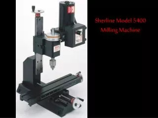
The Milling Machine. Care and Maintenance of Milling Cutters. The life of a milling cutter can be greatly prolonged by intelligent use and proper storage.

E N D
Care and Maintenance of Milling Cutters • The life of a milling cutter can be greatly prolonged by intelligent use and proper storage. • Take care to operate the machine at the proper speed for the cutter being used, as excessive speed will cause the cutter to wear rapidly from overheating. • Take care to prevent the cutter from striking the hard jaws of the vise, chuck, clamping bolts, or nuts. • Whenever practical, use the proper cutting oil on the cutter and workpiece during operations, since lubrication helps prevent overheating and cutter wear. • Keep cutters sharp. Dull cutters require more power to drive and this power, being transformed into heat, softens the cutting edges. Thoroughly clean and lightly coat milling cutters with oil before storing. • Place cutters in drawers or holders so that their cutting edges will not strike each other. • Never operate a cutter backwards.
Checklist Before you enter work area • Put on safety glasses • Tie back loose hair and clothing • Remove jewelry including rings, bracelets, and wristwatches • Do not use any piece of equipment until instructor has demonstrated proper operational procedures and individual safety rules • Do not use any equipment or tools that are broken and report any broken equipment or tools immediately
Checklist Before machining a part • While setting up work, install the cutter last to avoid being cut. • When installing or removing milling cutters, always hold them with a rag to prevent cutting your hands. • Make sure you have the correct tool for the job. • Secure the tool properly. • Make sure all tool positions have been properly initialized. • Verify the NC program on the computer before machining. • Remove all loose parts and pieces from the machine. • Remove adjusting keys and wrenches from the machine. • Close the safety shield.
Checklist • Before machining a part • Perform a dry run. • Set the spindle motor switch to lowest manual speed setting. • Make certain there is no work piece in place. • Run the NC program to make sure all the moves make sense before running the program with a work piece in place. • After completing the dry run, properly secure the work piece to the machine. • Keep fluids away from all electrical connections, electronic or electrical devices, the computer, and nearby electrical outlets.
Checklist While machining a part • Do not touch moving or rotating parts. • Do not place or remove anything from the work area while machine is running. • Press the Emergency Stop button before re-opening the safety shield. • Only open the safety shield after the spindle has stopped rotating. • Press the Emergency Stop button whenever changing tools or mounting or removing a work piece. • Pull the Emergency Stop button out only after closing the safety shield. • Keep all unauthorized persons away from the work area. • Always leave work area clean and orderly.
CNC Speed and Feed Capabilities • Prolight 1000 • Linear Feed Rate • 0.1 – 25 ipm • (2 – 635 mm/min) • Circular Feed Rate • 0.1 – 18 ipm • (2 – 457 mm/min) • X,Y Rapid Feed • 50 ipm • (1270 mm/min) • Z Rapid Feed • 40 ipm • (1016 mm/min) • Speed Range • 0 - 5,000 RPM Super Prolight 1000 Linear Feed Rate • 0.1 – 75 ipm • (2 – 1905 mm/min) Circular Feed Rate • 0.1 – 75 ipm • (2 – 1905 mm/min) X,Y Rapid Feed • 75 ipm • (1905 mm/min) Z Rapid Feed • 75 ipm • (1905 mm/min) Speed Range • 0 - 5,000 RPM
CNC Prolight Z Axis Stepper Drive Motor Safety Shield Cross Slide Spindle Motor Spindle Head X Axis Stepper Drive Motor Y Axis Stepper Drive Motor 1 1 4 2 5 3 6 4 2 5 3 6 7 7
Manual Control Panel • Manual Spindle Speed • Emergency Stop • Manual to CNC Switch
Low Profile Clamping Kit One Axis Pneumatic Vise Step Blocks and Strap Clamps 2 Axis Pneumatic Vise Other Vises / Hold Downs
Loading / Changing a Quick Change Collet • Move the Z axis to a safe location • Press the emergency button • Open the safety shield • Insert the chuck lock pin
Milling Bits SpecialtyTools Common Tools Double End Bit Roughing End Mill Long End Mill Engraver Edge Finder in Tool Holder
Machine Zero / Home +Z +X +Y -X -Y -Z
Part Zero +Z +X +Y -X -Y -Z
CNC Machine Axes PRZ • Part Reference Zero • Origin • 0,0,0 +Z -Z +X +Y -Y -X
- x offset = D/2 (0,0,0) PRZ Position Cutting Tool - y offset = D/2 Part Reference Zero (PRZ) Position Yp D= tool diameter Top View Work Piece Ym Xp Part Axes Xm Machine Axes
Part Reference Zero (PRZ) Position Zp Front View Xp Work Piece (0,0,0) PRZ Position Note: x offset = y offset = D/2 z offset= 0
Checking PRZ Send the Mill to a point above the x and Y zero to make sure the center of the cutting tool is over the top front corner.
True Spin Not Touching Material Offset Spin (Jump) Touching Material Using an Edge Finder Edge finders are used to find X & Y Edge, not Z (Top) Surface
Tool Setup The first step in setting up a tool library is to home the machine. The homing process will send the mill to a known position along all three axes. Follow the steps below to home the machine. • Select Setup in the menu bar and then Set/Check Home • Hold the Control key and type H • Right click on the Jog Control Panel and select Set/Check Home • Select the Home icon from the tool bar Home
Tool Height Offset Tool Height Offsets When a tool offset is established, the control program calculates its height move using the offset. Where does the mill spindle go when it is directed to a height of .5?
Tool Setup Wizard A wizard is available for setting up tools. Select Tool - Setup Tool Wizard from the main menu. Click Next The first tool established a reference height.
Tool Setup Wizard To put the reference tool in the spindle, click here. Click on Next.
Tool Setup Wizard Offset gage - Works as a continuity check. The light shines when a complete circuit is made by touching the tool and table. Click Next to continue. After inserting the reference tool, use the jog control panel to put the end of the cutting tool on the top of the block.
Tool Setup Wizard Remove the Reference tool and then select Next. You’re Done! Note that the Z coordinate in the Position Panel changes to zero. The current height is now the reference point. All other tools heights will now be compared to this.
Tool Setup Wizard If the tool library has other tools defined, you may now select them to set the tool height offset. If the tool is not in the library, you will need to set it up.
Setting Up the Tool Library Type in a tool description. Enter the diameter. Select the tool number. This will be identified as tool 1 (M06T1).
An End Mill has a flat bottom. Center cutting is recommended since plunging is often required. Setting Up the Tool Library Select the type of tool. A Bull Mill has a nose radius on its corners - Define the radius here.
Setting Up the Tool Library An engraving tool is a type of tapered cutter. Select the type of Tool Define the taper angle A Ball Mill has a constant radius (1/2 diameter) on its end. Define the diameter at its end point A Standard Drill (118° Point).
Setting Up the Tool Library Load the tool in the spindle and set the parameters.
Setting Up the Tool Library Jog the machine so the tool is touching the top of the reference point (Tool offset Gage)
Set the tool Height offset by clicking Current Z. Setting Up the Tool Library
Note that the position panel shows a z height of zero. The control software has calculated the difference between the reference tool and tool 1. Setting Up the Tool Library
Setting Up the Tool Library Tool Height offset
Setup Tool Library Station locations are used for mills equipped with automatic tool changers. Identify tool material (high speed steel is a good general purpose tool). Number of teeth (flutes) in the cutting tool. Always apply any changes before continuing to the next tool.