Download
1 / 30
300 likes | 310 Views
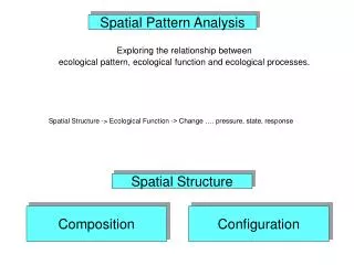
Spatial Analysis. Spatial Analysis. Proximity (ARC) pointdistance near Buffering (ARC) buffer Polygon Overlay (ARC) clip split erase update union intersect identity. No attribute merging. with attribute merging. Proximity Calculations.

E N D
Spatial Analysis POEC 6382 Applied GIS Software
Spatial Analysis • Proximity (ARC) • pointdistance • near • Buffering (ARC) • buffer • Polygon Overlay (ARC) • clip • split • erase • update • union • intersect • identity No attribute merging with attribute merging POEC 6382 Applied GIS Software
Proximity Calculations • POINTDISTANCE computes the distances between point features in one coverage to all points in a second coverage that are within the specified search radius. POINTDISTANCE <from_cover> <to_cover> <out_info_file> {search_radius} POEC 6382 Applied GIS Software
Proximity Calculations, page 2 • NEAR computes the distance from each point in a coverage to the nearest arc, point or node in another coverage. NEAR <in_cover> <near_cover> {LINE | POINT | NODE} {search_radius} {out_cover} {NOLOCATION | LOCATION} Arc: near well stream line 1500 wellstr location The PAT of the output coverage will have two additional items: one to store the distance to the nearest feature in the near_cover, and a second to store the internal number of the nearest feature. LOCATION adds items for x and y coordinates. POEC 6382 Applied GIS Software
BUFFERING • BUFFER creates polygon coverages by generating buffer zones around input coverage features (lines, polygons, points, or nodes). • BUFFER <in_cover> <out_cover> {buffer_item} {buffer_table} {buffer_distance} {fuzzy_tolerance} {LINE | POLY | POINT | NODE} {ROUND | FLAT} {FULL | LEFT | RIGHT} • {buffer_item} - an item in the feature attribute table of <in_cover> whose value is used as the feature’s buffer distance. • {buffer_table} - an INFO lookup table which lists a buffer distance for each {buffer_item}. A {buffer_table} can be specified only if {buffer_item} is specified. • {buffer_distance} - the distance used to create buffer zones around <in_cover> features when {buffer_item} or {buffer_item} and {buffer_table} are not specified. DISTANCE must be defined as a numeric item (i.e., N, I, F, or B) • {LINE | POLY | POINT | NODE} - the feature class to be buffered. POEC 6382 Applied GIS Software
BUFFERING, pg 2 • Output coverages are always polygon coverages • The size of the buffer zone is defined in one of three ways: • By using the buffer distance to specify a constant size for all buffer zones • Arcplot: buffer roads roadbuf # # 4 # line • By specifying an item value to generate multiple buffer sizes directly • Arcplot: buffer roads roadbuf distance # # # line • By generating the multiple sized from item values through a lookup table • Arcplot: buffer roads roadbuf type road.lut # # line BUFFER <in_cover> <out_cover> {buffer_item} {buffer_table} {buffer_distance} {fuzzy_tolerance} {LINE | POLY | POINT | NODE} {ROUND | FLAT} {FULL | LEFT | RIGHT} • The PAT of the output coverage will have an additional item called INSIDE. The INSIDE value for each record will be one of the following: 100 Area is inside zone/buffer 1 Area is outside zone/buffer POEC 6382 Applied GIS Software
BUFFERING, pg 3 BUFFER <in_cover> <out_cover> {buffer_item} {buffer_table} {buffer_distance} {fuzzy_tolerance} {LINE | POLY | POINT | NODE} {ROUND | FLAT} {FULL | LEFT | RIGHT} POEC 6382 Applied GIS Software
POLYGON OVERLAY • POLYGON OVERLAY commands involve three coverages: an input coverage, an overlay coverage, and an output coverage created as a result of the overlay. • Input coverage features can be polygons, lines, or points. • The overlay coverage feature must be polygons. • Output coverage features are of the same class as the input coverage features. • polygon-on-polygon overlay - output is a polygon cover • line-on-polygon overlay - output is an arc coverage • point-on-polygon overlay - output is a point coverage • CLIP, ERASE, SPLIT, UPDATE, UNION, INTERSECT, IDENTITY with attribute merging No attribute merging POEC 6382 Applied GIS Software
CLIP • CLIP - extracts those features from an input coverage that overlap with a clip coverage. This is the most frequently used polygon overlay command to extract a portion of a coverage to create a new coverage. CLIP <in_cover> <clip_cover> <out_cover> {POLY | LINE | POINT | NET | LINK | RAW} {fuzzy_tolerance} The <clip_cover> must have polygon topology. Boundaries of interior polygons in the <clip_cover> are not used in CLIP. CLIP uses the clip coverage as a cookie cutter; only those input coverage features that are within the clip coverage are stored in the output coverage. Topology is built for the output coverage. Only the attributes of the in_cover are retained in the out_cover POEC 6382 Applied GIS Software
CLIP, pg 2 POEC 6382 Applied GIS Software
Clipping an Image • Clipping of images is fundamentally different from clipping coverages. This is because images are a raster data format while coverages are a vector format. There are several ways to clip an image. The most straightforward way is given herein. • Use the RECTIFY command, specifying a clip BOX or clip_cover on the command line. Note that the clip_cover area is defined by the BND of the coverage, not the polygon features in the coverage. • An image is always rectangular, so it can only be clipped with a rectangular box or BND. POEC 6382 Applied GIS Software
ERASE • ERASE - erases the input coverage features that overlap with the erase coverage polygons. ERASE <in_cover> <erase_cover> <out_cover> {POLY | LINE | POINT | NET | LINK | RAW} {fuzzy_tolerance} The <erase_cover> must have polygon topology. Boundaries of interior polygons in the <erase_cover> are not used in ERASE. The polygons of the erase coverage define the erasing region. Input coverage features that are within the erasing region are removed. The output coverage contains only those input coverage features that are outside the erasing region. Erase is the opposite of clip: it leaves you with “the left over dough” Topology is rebuilt for the output coverage. POEC 6382 Applied GIS Software
ERASE POEC 6382 Applied GIS Software
SPLIT • SPLIT - breaks a single coverage into many coverages. • SPLIT <in_cover> <split_cover> <split_item> {POLY | LINE | POINT | NET | LINK | RAW} {fuzzy_tolerance} • <split_item> - the item in <split_cover> which will be used to split the <in_cover>. • You will be prompted to enter the names of output coverages and <split_item> values • Up to 50 output coverages can be specified. • The <split_cover> must have polygon topology. Arc: split maptile index tilename poly 1.0 When done entering coverages, type END or a blank line. Enter the 1st coverage: tilesplit1 Enter item value: tile3 Enter the 2nd coverage: tilesplit2 Enter item value: tile4 Enter the 3rd coverage: end POEC 6382 Applied GIS Software
SPLIT, page 2 POEC 6382 Applied GIS Software
UPDATE • UPDATE - replaces the input coverage areas with the update coverage polygons using a cut-and-paste operation. • UPDATE <in_cover> <update_cover> <out_cover> {POLY | NET} {fuzzy_tolerance} {KEEPBORDER | DROPBORDER} • {KEEPBORDER | DROPBORDER} - specifies whether or not the outside border of the <update_coverage> will be kept after it is inserted into the <in_cover>. • UPDATE uses the updating extent in a ‘cut-and-paste’ operation; update coverage features replace the area they overlap in the input coverage. The result is stored in the output coverage. • Both the input and update coverages must have polygon topology. • Topology is rebuilt for the output coverage. • Attributes are also updated. Items in the PAT are merged using the old internal number of each polygon. POEC 6382 Applied GIS Software
UPDATE, page 2 POEC 6382 Applied GIS Software
UPDATE, page 3 POEC 6382 Applied GIS Software
Polygon Overlay with Attribute Merging • There are three commands that perform polygon overlay that merge attribute data: UNION, INTERSECT, and IDENTITY • UNION combines all the features of both coverages • INTERSECT Only those features in the area common to both coverages will be preserved in the output coverage. Any data that lie outside the common area are deleted (clipped) from the output coverage. • IDENTITY All features of the input coverage, as well as those features of the identity coverage that overlap the input coverage, are preserved in the output coverage. POEC 6382 Applied GIS Software
Union • UNION - computes the geometric intersection of two polygon coverages. All polygons from both coverages will be split at their intersections and preserved in the output coverage. • UNION <in_cover> <union_cover> <out_cover> {fuzzy_tolerance} {JOIN | NOJOIN} • {JOIN | NOJOIN} - specifies whether all items in both the <in_cover> PAT and <union_cover> PAT will be joined into the output coverage PAT. POEC 6382 Applied GIS Software
INTERSECT • INTERSECT - computes the geometric intersection of two coverages. Only those features in the area common to both coverages will be preserved in the output coverage. • INTERSECT <in_cover> <intersect_cover> <out_cover> {POLY | LINE | POINT} {fuzzy_tolerance} {JOIN | NOJOIN} POEC 6382 Applied GIS Software
INTERSECT, page 2 POEC 6382 Applied GIS Software
IDENTITY • IDENTITY - computes the geometric intersection of two coverages. All features of the input coverage, as well as those features of the identity coverage that overlap the input coverage, are preserved in the output coverage. • IDENTITY <in_cover> <identity_cover> <out_cover> {POLY | LINE | POINT} {fuzzy_tolerance} {JOIN | NOJOIN} POEC 6382 Applied GIS Software
IDENTITY, Page 2 POEC 6382 Applied GIS Software
Solving Problems Through Spatial Analysis • Extract features from a coverage to create a new coverage • Create zones around features • Combine coverages to create new data relationships • Develop models • Identify trends • Make better decisions POEC 6382 Applied GIS Software
Typical Steps in Spatial Analysis • Establish analysis objectives and criteria • Prepare data for spatial operations • Perform spatial operations • Prepare derived data for tabular analysis • Perform tabular analysis • Evaluate and interpret results • Refine the analysis as necessary • Produce final maps and tabular reports of the results POEC 6382 Applied GIS Software
Spatial Analysis Example, page 1 • Your firm has been contracted to identify sites that are suitable for a landfill. An ideal site would meet the following criteria: • At least 1/4 mile from any local street • Soil suitable for landfill development • Zoned industrial or agricultural • Vacant or agricultural land use • Not prone to flooding • Not within a fault zone • Area greater than 1,400,000 square feet • Coverages available: • 1. streets 4. landuse • 2. soil 5. flood • 3. zoning 6. faultzone POEC 6382 Applied GIS Software
Spatial Analysis Example, page 2 • STEP 1: BUFFER streets for 1/4 mile (1320 feet) • STEP 2: UNION the street buffer coverage with soils, flood, zoning, landuse, and faultzone (all polygon on polygon with join). Add an item to the final coverage called suitable. • STEP 3: RESELECT (in Arcplot) from the resulting coverage, buffer item INSIDE = 1 (to select areas outside the buffer polygon), soiltype = clay, flood = outside, zone = industrial or zone = agricultural, landuse = vacant or landuse = agricultural, and faultzone = outside. • STEP 4: Once the polygons are selected, calculate suitable to be equal to 1. Combine polygons for which suitable = 1 (dissolve on suitable). Reselect polygons with area>1400K POEC 6382 Applied GIS Software
Spatial Analysis Example #2 • Identify suitable sites (from 6 possible locations) for a branch bank: • more than 10,000 population within 2 miles • no other bank within 1 mile • on a parcel adjacent to a major thoroughfare • Available coverages: • 6parcels • census • banks • roads POEC 6382 Applied GIS Software
Spatial Analysis Example #3 • Design a sensitive habitat preservation zone for the purple-throated tutsi bird (very rare), which needs: • grassland, area over 1,000 acres • adjacent to forest, area over 500 acres • no major road within 5 miles. • What data (coverages) do I need? POEC 6382 Applied GIS Software