Download
1 / 43
440 likes | 696 Views
Paralytic Twitch Sensor. Sponsored by: Dr. Thomas Looke and Dr . Zhihua Qu. Group 14 Kelly Boone Ryan Cannon Sergey Cheban Kristine Rudzik. Motivation . Techniques for evaluating levels of muscle response today are not reliable.

E N D
Paralytic Twitch Sensor Sponsored by: Dr. Thomas Looke and Dr. ZhihuaQu Group 14 Kelly Boone Ryan Cannon Sergey Cheban Kristine Rudzik
Motivation Techniques for evaluating levels of muscle response today are not reliable. • Anesthesiologist as the sensor: by touch or by sight • Other methods require patients arms to be restrained • Problems: if restrained wrong it could lead to nerve damage in the patient or false readings Seeing first hand when we shadowed Dr. Looke individually • Trying to find a way to not let the blue shield that separates the sterile field create an inconvenient way to measure the twitches.
Medical Background Anesthesia • Nobody is really sure how it works; all that is known about these anesthetics: • Shuts off the brain from external stimuli • Brain does not store memories, register pain impulses from other areas of the body, or control involuntary reflexes • Nerve impulses are not generated • The results from the neuromuscular blocking agents (NMBAs) are unique to each individual patient. Therefore there is a need for constant monitoring while under anesthesia.
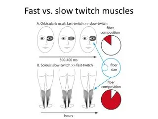
Medical Background Different types of measuring: • The thumb (ulnar nerve) • Most reliable and accurate site • Easy to access • The toes (posterior tibial nerve) • Fairly accurate alternative • Difficult to reach • The eye (facial nerve) • Not an accurate way to measure
Medical Background 3 main stimulation patterns that need to be included in the design: • Tetanic • Single-Twitch • Train-of-Four (TOF)
Medical Background Tetanic Stimulation • The concept of using a very rapid delivery of electrical stimuli at maximum current. • Used once patient is unconscious, before the induction of anesthesia, to obtain a baseline measurement. • Frequency impulse commonly used is 50 Hz for a maximum duration of 5 seconds.
Medical Background Single-twitch Stimulation • The simplest form of nerve stimulation; the concept of using a single electrical stimulus at a constant frequency. • Used to view the onset of the neuromuscular block up until muscle response is first detected. • Stimulation frequency varies between 1 Hz (equivalent to one stimulation every second) and 0.1 Hz (i.e., one stimulus every 10 s). Injection of NMBA
Medical Background Train-of-Four (TOF) Stimulation • Involves four successive stimuli to the target motor nerve. • Stimulation occurs every 0.5 seconds, resulting in a frequency of 2 Hz, and a 10-second delay between each TOF set. • Used once muscle response is detected. • TOF Ratio: assesses the degree of neuromuscular recovery • T4/T1 Pattern of electrical stimulation and evoked muscle response before and after injection of neuromuscular blocking agents (NMBA).
Goals • Sensor that is relatively accurate • An interactive LCD touchscreen • Minimal delay between the sensed twitch and the read out • Train-of-Four (TOF), single twitch and tetanic stimulation patterns • Safe to use in the operating room • Any part that touches the patient needs to either be easily cleaned or inexpensive enough to be disposed of after each use
Specifications • A maximum current of at least 30mA • Maximum charge time of 0.5 seconds in order to have a reliable train of four • Minimum sampling frequency of 100Hz • Consistent sensor readout accuracy of ±25% • The sensor readout is within 5% of the actual value
Inductive-Boost Converter • Uses the inductor to force a charge onto the capacitor • 555 timer provides reliable charging • Microcontroller triggered delivery
Voltage Multiplier • Built using a full wave Cockcroft–Walton generator • Every pair of capacitors doubles the previous stages’ voltage • Vout= 2 x Vin(as RMS) x 1.414 x (# of stages)
Voltage Multiplier • To reduce sag in the multiplier, positive and negative biases were added to the previous circuit.
Force-Sensitive Resistors (FSRs) 4 in. A201 Model 0.55 in. 1 in. A301 Model
Pressure Sensor Requirements • Gauge pressure sensor • Only measures a positive input range • Small accuracy error • Quick response time
Freescale MPXV5010GP Pressure Sensor • Internal amplification • Low pass output to avoid noise • Quick response time, tR, of 1.0 msec • Required • 5 V input • 5 mA constant current input • Input Range: 0 – 10 kPa (0 – 1.45 psi) • Output Range: 0.20 – 5.00 V Transfer Function Vout = Vin * (0.09 * P + 0.04) ± ERROR where P = pressure in kPa
Electromyography (EMG) Sensor • Optional method of monitoring if preferred by the anesthesiologist. • EMG records the electrical activity of a muscle at rest and during contraction. • EMG sensor indirectly measures neuromuscular blockades by finding the compound action potentials produced by stimulation of the peripheral nerve
Microcontroller Important Features • Low cost • Large developer support • Enough FLASH memory • Libraries Available • Works with our LCD display • Preferably through-hole package
LCD Display 4d-systems uLCD-43-PT Itead Studio ITDB02-4.3 • 4.3” display • Easy 5-pin interface • Built in graphics controls • Micro SD-card adaptor • 4.0V to 5.5V operation range • ~79g • Has already been used in medical instruments • ~$140.00 • 4.3” display • 16bit data interface • 4 wire control interface • Built in graphics controller • Micro SD card slot • ~$40.00 • Not enough information
4D-Systems uLCD-43-PT Delivers multiple useful features in a compact and cost effective display. • 4.3” (diagonal) LCD-TFT resistive screen • Even though it’s more expensive than the other screen we know that this screen works and it has already been used in medical devices. • It can be programmed in 4DGL language which is similar to C. • 4D Programming cable and windows based PC is needed to program
PICASO-GFX2 Processor • Custom Graphics Controller • All functions, including commands that are built into the chip • Powerful graphics, text, image, animation, etc. • Provides an extremely flexible method of customization
Power Supply • Initial power from Wall Plug, used for Voltage Multiplier • Converted to 5V and 3.3V for use with ICs • Backup: modified laptop charger
Voltage Regulators • LDO vs. Switching • Both got up to almost 200˚ • Decided to go with LDOs for simplicity because power was not an issue. • LM7805 and LM7812
Testing: FlexiForce Sensor Per instruction by Tekscan’s website: • Tested sensor on a flat, hard surface. • Calibrated the sensor with 110% of the maximum load until steady output was maintained. • Used a shim between the sensing area and load to ensure that the sensor captures 100% of the applied load since the thumb is larger than the 0.375-inch sensing area. • Used the recommended circuit shown, with reference resistance, RF, varying between 10kΩ and 1MΩ. Metal shim with a 0.325-inch diameter. Recommended circuit provided by Tekscan.
Testing: FlexiForce Sensor • Attached the shim to the bottom of the center of the metal shot glass. • Added lead bullet weights to the shot glass in increments of 3 and saw how the output changed with the increasing load. Shim attached to Lead bullet weights shot glass
Testing: Pressure Sensor • The pressure sensor is connected to an inflatable pessarywhich is placed in the patient’s hand • The pressure sensor will measure the strength of the muscle response by how much air pressure results from the squeeze of the pessary.
Testing: Pressure Sensor • Used a flat surface on top of the pessary to evenly distribute the force applied on the pessary • Tested MPXV5010GP pressure sensor in a similar way to the FlexiForce: • Measured with a constant force by adding the lead pellets, which were applied evenly over the pessary • Incremented the force applied to the pessary at a constant rate • Measurements showed a more linear result than the Flexiforce • Important for TOF ratio
User Interface/ testing • Top: • Screen for adjusting the current level and the interval of the twitches (for single twitches and groups of TOF) • Bottom: • Choosing which nerve stimulation type • Graph of the outputs • TOF ratio
Issues • Testing and demonstrating the final product • Generating the appropriate voltage • Picking an accurate enough sensor • Inaccurate information on the datasheet • The screen pulled 260 mA of current when the datasheet said it would only pull a maximum of 150 mA