Download
1 / 41
410 likes | 492 Views
PS 2.2. High Flexibility Rotorcraft Driveshafts using Flexible Matrix Composites and Active Bearing Control Principal Investigators Kon-Well Wang, Ph.D. Diefenderfer Chaired Professor in Mechanical Engineering Charles Bakis, Ph.D. Professor of Engineering Science and Mechanics

E N D
PS 2.2 High Flexibility Rotorcraft Driveshafts using Flexible Matrix Composites and Active Bearing Control Principal Investigators Kon-Well Wang, Ph.D. Diefenderfer Chaired Professor in Mechanical Engineering Charles Bakis, Ph.D. Professor of Engineering Science and Mechanics Edward Smith, Ph.D. Professor of Aerospace Engineering Graduate Student supported by RCOE Bryan Mayrides (M.S. student) Other Team Members Hans DeSmidt (Ph.D. student) Ying Shan (Ph.D. student)
Bearings Couplings Issues applicable to both helicopter and tiltrotor Issues of Current Driveline Systems – Problem Statement and Technical Barriers • Current Drivelines • Segmented shafting with significant # of flex couplings/bearings for misalignment compensation • Passive dampers needed for supercritical speed shafts • High Maintenance and Cost • Component (bearings, couplings, dampers) wear • Shaft balancing and alignment • Strict shaft eccentricity tolerances
Program Goal and Ideas To address the issues with current systems and overcome the technical barriers for achieving a simple, high performance, low vibration, low cost, and low maintenance driveline of rotary-wing aircraft • Reduce number of mechanical contact components • Reduce maintenance need • Suppress vibration and ensure stability Develop and utilize newly emerging materials and active control technologies -- a combination of • Flexible matrix composite(FMC) materials and • Active magnetic bearings (AMB) IDEAS ?
AMBs FMC shaft Bearings Couplings New Current Ideas Flexible matrix composite (FMC) materials with tailored ply orientations for shafting • Soft in flexure and stiff in torsion – to accommodate for large misalignment and effectively transmit power • Withoutmulti-segment shafting and large # of bearings/couplings -- reduce cost and maintenance need
Active magnetic bearings for low maintenance and vibration control While highly flexible composite driveshaft systems have many advantages, their vibration behavior could be issues that need to be addressed before realizing the idea Penn State researchers have explored the feasibility of active vibration control of tailrotor-drivetrain structure via active magnetic bearings (AMB) by proper controller design, the AMB actuator could be a good candidate for helicopter driveline control (size, weight, power) [DeSmidt, Wang, and Smith, Proc of 54th AHS Forum, 1998] Non-contact -- no frictional wear Large frequency range -- ideal for active vibration control in rotorcraft setting Light backup roller bearings (only contact with active failure) for fail-safe purpose Electro-Magnetic Coil Stator Shaft Airgap Ideas (cont.)
2004 Review Comments and Actions • Assess Potential Payoffs • We have examined payoffs for supercritical driveline in previous studies; this year we expanded the study to show potential payoffs (weight and component reductions) for subcritical drivelines via system design • Assess Cost Benefit • Qualitatively, reducing components/maintenance = reducing cost; • To quantify cost benefit requires development on specific drive system with manufacturers and users (future RITA project) • Examine Practicality of Magnetic Bearing • Have achieved another successful demonstration of AMB controller for FMC shafting with uncertainties • In the process of examining AMB design (weight, size, power) in rotorcraft setting via NASA Glenn design code (On-going effort) • Have generated new ideas of hybrid active-passive failsafe devices as future basic research topics • Address Failure Modes • Thorough study beyond scope of current program – Have generated ideas/plan to examine this issue as a future basic research topic
Research Issues and Task Objectives • Materials and Composite Issues • Structural Mechanics and Dynamics Issues • Systems and Controls Issues
FMC RMC Matrix Cracking 0 0 90 90 0 90 0 0 90 0 90 90 90 Research Issues and Task Objectives • Materials and Composite Issues • Rationale: • Traditional barrier to higher strain operation of fiber composites is matrix cracking • Flexible, low-modulus matrix can potentially avoid cracking • Technical Objectives: • Select a trial flexible matrix system (carbon/polyurethane) • Develop filament winding process • Characterize stiffness & damping behavior and validate models over range of temperatures, frequencies, and strains • Build lab-scale shafts for experimental validation of self-heating, structural dynamics, and to investigate fatigue behavior Matrix Cracking
Achievements 2001-2003/04 Developed wet filament winding technique for trial flexible matrix composite shafts (carbon/polyurethane) Developed test apparatus & method for characterizing frequency and temperature dependent damping & stiffness of FMC laminas and laminates Developed & validated models for frequency and temperature dependent damping & stiffness of FMC laminas and laminates Developed model and test method to investigate self-heating behavior of rotating misaligned FMC shafts Summary of Accomplishments in 2004/05: Refined and experimentally validated self-heating model of rotating misaligned FMC shafts Materials and Composite Sub-Task
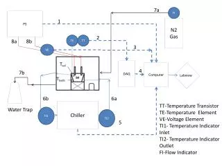
y Misaligned Rotating Shaft Test Stand for Model Validation and Fatigue Characterization r Shaft Self-Heating Model z a b T1 Ti-1 Ti Ti+1 Tn-1 Zoom In Tn T0 P r Convection into air (T) due to rotation Insulated o a x r/2 r/2 M b Ti, r 5 ft Internal Self-Heating Model and Experimental Validation Method for Misaligned Rotating FMC Shafts • Input to the temperature model: frequency and temperature dependent lamina properties of FMC material; misalignment strain; shaft speed • The misalignment strain and rotation speed can be controlled. The stand can spin FMC shafts at up to 1.25% misalignment strain, and at speed up to 2500 RPM
0.25%, RMC 0.25%, FMC Model Results and Experimental Validation (±45) deg. FMC 0.75%, RMC 0.75%, FMC • Model capable of predicting self heating behavior of FMC materials and providing guidance for design and control of FMC shaft • Self-heating of FMC shaft is insignificant compared to RMC
Effect of Temperature on Shaft Properties Shaft Longitudinal Modulus • Laminate design affects temperature sensitivity of shaft • Tool developed can predict temperature effect on shaft properties provide design and control guidance [+60/-60/+25/-25]s [+45/-45/+45/-45]s
Research Issues and Task Objectives • Materials and Composite Issues • Structural Mechanics and Dynamics Issues • Develop analysis tools for driveshaft dynamic loads/ deformation characterization (e.g., strain level, buckling, stability, damping effect on temperature & property variation) • FMC materials selection and structural tailoring/optimization to satisfy design desires (e.g., maximum allowable misalignment, minimum weight, and minimum internal damping) • Systems and Controls Issues
Structural Mechanics and Dynamics Sub-Task • Summary of Previous Work (2001-2003/04) • FE model and analysis tools have been developed to analyze driveline static and dynamic characteristics (deformation,stress level,natural frequency, etc.) • Utilizing the model and tools developed, • Performed study to provide information regarding parameter effects on system (durability, stability, etc.) • System parameters were tailored to achieve satisfactory system performance for supercritical driveline
Structural Mechanics and Dynamics Sub-Task • Summary of Current Work (2004/05) • Examined feasibility of designing FMC driveshafts for subcritical applications • Maintain advantages of current supercritical driveline (light weight, fewer bearings) but without the shortcomings (high vibration, whirl instability, and external damper requirements) • Performed optimization study where shaft parameters were tailored to find minimum weight and/or component driveline that meets performance requirements • Examined applications for model/analysis tool • Reducing weight in subcritical driveline (Blackhawk, Chinook) • Design a driveline for a minimum number of components
Design Approach/Model Outline • Inputs • Helicopter properties (shaft geometry, speed, power) • Applied loads (torque, misalignment, imbalance) • Design variables (ply sequence, ply angles, # bearings, outer diameter) • Inputs used to iteratively calculate temperature dependent laminate properties and steady state temperature • Accounts for self-heating (misaligned rotation) and considers atmospheric heating and rotor downwash cooling • Laminate properties (at steady state temperature) to calculate performance indices • Critical speed ratio (ensures subcritical) • Tsai Wu strength factor (measure of strength) • Torsional buckling safety factor • Torsional yield safety factor • Driveline with minimum weight/components is “optimum” design
New - FMC Minimum Weight Design Study Results - Blackhawk • Blackhawk: current driveline specifications • 5 segments • 4 midspan flex couplings, 4 midspan bearings • Driveline mass = 31.3 kg (69 lbs) • Blackhawk: optimum FMC driveline specifications • 1 segment with [60/-60/-25/25]S layup • 0 midspan couplings, 3 midspan bearings • Driveline mass = 21.6 kg (47.6 lbs) • (reduction of 5 components) • (reduction of 29.5%) Input Torque 734 Nm Conventional – Alloy
Conventional - Alloy New - FMC Minimum Weight Design Study Results - Chinook Conclusion: Designers go from subcritical to supercritical to reduce weight, but weight savings (even component reduction) can also be realized by using FMC drivelines while maintaining subcritical operation • Chinook: current driveline specifications • 7 segments • 6 midspan flex couplings, 6 midspan bearings • Driveline mass = 60.4 kg (133 lbs) • Chinook: optimum FMC driveline specifications • 1 segment with [50/-50/-20/20]S layup • 0 midspan couplings, 5 midspan bearings • Driveline mass = 44.4 kg (97.9 lbs) • (reduction of 7 components) • (reduction of 25.5%) Input Torque 4067 Nm
Minimum Component Design Study • Observations: • Always eliminate all midspan couplings for FMC designs (both methods) • The number of bearing components can be further reduced even with subcritical speed requirement • Weight still saved for this case as compared to current design • Model & analysis tool applied to re-design driveline for minimum components (reduce maintenance needs) instead of minimum weight • Can we still achieve weight savings when minimizing driveline components? • One example: Blackhawk with [q1/-q1/-q2/q2]slayup
Research Issues and Task Objectives • Materials and Composite Issues • Structural Mechanics and Dynamics Issues • Systems and Controls Issues • Effective vibration and stability control methodology • Vibration suppression -- Shaft imbalance with uncertain magnitude and distribution • Stability issues for supercritical shafting -- whirl instability due to shaft internal damping • Adaptive control to compensate for operating condition uncertainty and shaft property variations • Actuator/system design in rotorcraft setting (size, weight, power)
Systems and Controls Sub-Task- Achievement Summary • Achievements (2001- 2003/04) • Preliminary study to identify issues and feasibility of AMB actuators/control in rotorcraft setting • Developed state equation and uncertainty function formulation for the AMB-FMC driveshaft system • Synthesized hybrid robust feedback/adaptive feed-forward control law for AMB driveline system and developed robust controller design methodology • Analytically and experimentally evaluated and validated closed-loop controller performance on AMB-driveline testrig (on conventional segmented Alloy shaft)
Systems and Controls Sub-Task • Summary of New Achievements (2004/05) • Developed H/Synchronous Adaptive Feed-Forward controller for AMB/FMC driveline system • Suppress imbalance vibration • Suppress whirl instability (if supercritical) • Account for FMC shaft stiffness and damping uncertainties due to operating temperaturevariations • Concurrent optimal design of control parameters and AMB locations to maximize closed-loop robustness • Analytically and experimentally evaluated AMB/FMC driveline closed-loop performance on testrig • Stability and vibration suppression performance and robustness • Multiple operating conditions (various shaft speeds, load torques, and operating temperatures)
Non-Contact Active Magnetic Bearing Hybrid H/AVC Control Law • Robust H feedback - Levitates driveline & ensuresstability • Adaptive feed-forward - Adapts to suppress driveline vibration AMB-FMC Driveline System with Hybrid H /Adaptive Control AMB-FMC Driveline System • One-Piece FMC shaft with rigid couplings supported by Active Magnetic Bearings (AMB) • Driveline subjected to shaft imbalance, misalignment, torque & ambient temperature variations
AMB-FMC Driveline SystemClosed-Loop Robustness & Performance • Due to FMC stiffness and damping temperature sensitivity, H/AVC designed to be robust to variations about nominal temperature • Closed-loop system has significant temp. robustness [ -20°F < T < 190°F] Test Results • Limited sensor information required • Only uses collocated AMB sensors • No knowledge of shaft imbalance or operating temperature required
Plan for rest of 2005 • Materials and Composite Issues • Evaluation of FMC fatigue behavior • Structural Mechanics and Dynamics Issues • Use structural dynamics model to select an “optimum” matrix material • Incorporate a safety factor in the model to design against fatigue failure • Systems and Controls Issues • Evaluate design issues (size, weight, power) of AMB actuator in rotorcraft setting via NASA Glenn AMB code • Compare weight/size with conventional bearing system
Overall Project Accomplishments & Conclusions We have shown, while maintaining torque transmitting capability • FMC shafting • Eliminates segments and flexible couplings/bearings – reduces components and maintenance needs • Reduces strict requirements for alignment • Reduces weight • AMBs • Eliminate contact bearings – reduce maintenance • Reduce vibration level with robust performance w.r.t. uncertainties (temperature, operating conditions, etc.) • Reduce strict requirements for balancing, alignment, and tolerance • The feasibility and advantages of utilizing FMC and AMB technologies to improve current rotorcraft driveline systems have been demonstrated for both super- and sub-critical drivelines • Tools have been developed which can be utilized for specific driveline system development applications • Manufacturing and characterization processes • Analytical and experimental methods • Design and control algorithms
Overall Project Future Directions • Application and development work (RITA type projects) • The analytical and experimental tools developed can be utilized for the development and evaluation of specific future drivelines with FMC shafting and/or AMB technology • Basic research possibilities • FMCs with materials enhancement (environment, fatigue, failure modes, etc.) for advanced rotorcraft applications • Active-passive hybrid non-contact bearings – Enhance driveline fail-safety and stability while retaining merits of AMBs • Distributed auto-balancing techniques – Enhance vibration reduction of driveline without active action
Publications • Shan, Y., and Bakis, C.E., “Static and Dynamic Characterization of a Flexible Matrix Composite Material,” Proc. 58th American Helicopter Society Annual Forum, Montreal, Quebec, June 2002. • Shan, Y., and Bakis, C.E., “Frequency and Temperature Dependent Damping Behavior of Flexible Matrix Composite Tubes,” 35th International SAMPE Technical Conference, Dayton, OH, Sept. 28 –Oct. 2, 2003. • Shin, E., Wang, K.W., and Smith, E.C., “Characterization of Flexible Matrix Composite Rotorcraft Driveshafts,” Proc. 59th American Helicopter Society Annual Forum, Phoenix, AZ, May 2003. • DeSmidt, H.A., Wang, K.W., Smith, E.C., and Provenza, A.J., “Stability Control of Driveline System with Internal Damping and Non-Constant Velocity Couplings,” Proc. ISCORMA-2 Conference, Gdansk, Poland, Aug. 2003.
Publications (Cont.) • DeSmidt, H.A., Wang, K.W., and Smith, E.C., “Multi-Harmonic Adaptive Vibration Control of AMB-Driveline Systems with Non-Constant Velocity Couplings,” Proc. ASME Design Technical Conference-19th Biennial Conference on Mechanical Vibration and Noise, Chicago, IL, Sept. 2003. • DeSmidt, H.A., Wang, K.W., and Smith, E.C., “Multi-Harmonic Adaptive Vibration Control of Magnetic Bearing-Driveshaft with Auxiliary Feedback: Theory and Experiment,” Proc. 45th AIAA Structures, Structural Dynamics and Materials Conference, Palm Springs, CA, April 2004. • DeSmidt, H.A., Wang, K.W., and Smith, E.C., ”Stability of a Segmented Supercritical Driveline with Non-Constant Velocity Couplings Subjected to Misalignment and Torque,” Journal of Sound and Vibration Vol. 277, No. 4-5, pp. 895-918, 2004. • DeSmidt, H.A., Wang, K.W., and Smith, E.C., “Adaptive Control of Flexible Matrix Composite Rotorcraft Drivelines,” Proc. 60th American Helicopter Society Annual Forum, Baltimore, MD, June 2004.
Publications (Cont.) • DeSmidt, H.A., Wang, K.W., Smith, E.C., and Provenza, A.J., ”On the Robust Stability of Segmented Driveshafts with Active Magnetic Bearing Control,” Journal of Vibration and Control, Vol. 11 pp.317-329, 2005. • Shan, Y., and Bakis, C.E., “Internal Heating Behavior of Flexible Matrix Composite Driveshafts,” Proc. 61st American Helicopter Society Annual Forum, Grapevine, Texas, 1-3 June 2005. • Mayrides, B., Wang, K.W., and Smith, E.C., “Analysis and Synthesis of Highly Flexible Helicopter Drivelines with Flexible Matrix Composite Shafting,” Proc. 61st American Helicopter Society Annual Forum, Grapevine, Texas, 1-3 June 2005. • DeSmidt, H.A., Wang, K.W., and Smith, E.C., “Multi-Harmonic Adaptive Vibration Control of Misaligned Driveshaft Systems – An Experimental Study,” Proc. of the 12th International Congress on Sound and Vibration, Lisbon, Portugal, July 2005.
External Interactions, Leveraging and Technology Transfer • Have had discussions with Army NASA Glenn (Bill, Provenza), Bell (Brunken, Riley), Boeing Philadelphia (Robuck, Gabrys), Boeing Mesa (Hansen), Lord Corporation (Potter), and UTRC (Davis) on various aspects of this project • Have worked with Army NASA Glenn on designing and fabricating test fixtures as well as Magnetic Bearing setup and calibration • Have visited Bell and discussed with Brunken and Riley – addressing temperature effect based on their suggestions; have continued discussion since then • Mark Robuck (Boeing Philadelphia) has visited Penn State in 2003 and discussed future collaboration possibilities in joining efforts for government contracts in this area – have continued to follow up • Leveraged upon Army/NASA Glenn GSRP Fellowship, Army DURIP, Weiss Fellowship, and internal funds from the Structural Dynamics and Controls Lab
Questions? The End
Near Term Mid Term Long Term Schedule and Milestones 2001 2002 2005 2003 2004 Tasks Refinement of driveline model Perform analysis on driveline model to provide info for FMC FMC selection/ synthesis FMC material characterization Structure tailoring/optimization AMB control law synthesis and overall system analysis Sub-scale shaft/test stand development Initial testing for validation of model and approach Refinement of material systems and processing methods Evaluation of FMC fatigue behavior Adaptive control design and closed-loop stability and performance analysis for FMC/AMB driveline system Concurrent system integration and analysis; AMB sizing and design for rotorcraft setting Integrated system testing and evaluation
Materials and Composite Sub-Task Key Accomplishments and Conclusions • Key Accomplishments • Developed manufacturing process for building FMC driveshafts • Characterized both static and dynamic properties of FMC driveshaft material • Developed models to predict self-heating behavior of misaligned FMC shafts from the basic lamina properties • Experimentally validated shaft self-heating model • Investigating FMC shaft fatigue behavior • Conclusion • FMC shaft material shows significant improvement on strain to failure, fatigue resistance, and self-heating behavior over the conventional composite materials • Despite the large damping capacity of FMC shaft materials, internal self-heating behavior of FMC shaft under misaligned rotating conditions is much less significant than that of RMC
Structural Mechanics & Dynamics Sub-Task- Key Accomplishments & Conclusions • Key Accomplishments • Developed versatile model and analysis tool to tailor FMC designs to meet certain performance standards • Applied model to supercritical drivelines to prove that FMC shafts can meet performance requirements • Showed possible weight saving advantage of FMC shafting by optimizing designs for specific subcritical drivelines (Blackhawk, Chinook) • Conclusion – Through selective tailoring of FMC driveshafts, the number of components and system weight can be reduced on helicopter drivelines • The single piece subcritical FMC driveline effectively addresses potential short comings of current drivelines • Eliminates mid-span flex couplings – decreases maintenance and replacement costs • Reduces overall system weight
Systems and Controls Sub-Task- Key Accomplishments & Conclusions • Key Accomplishments • Developed comprehensive AMB/FMC driveline dynamics analytical model • Developed feedback/adaptive feed-forward vibration and stability control strategy for AMB/FMC driveline which adaptively suppresses imbalance vibrations and is robust w.r.t. shaft temperature variations • Developed frequency scaled AMB/FMC driveline-foundation testrig • Experimentally implemented robust feedback/adaptive feed-forward control and validated AMB/FMC closed-loop performance at multiple operating conditions • Conclusion - Use of AMB with supercritical FMC driveline feasible & beneficial • The non-contact and active control aspects of AMB complement the low maintenance aspects of one-piece rigidly coupled FMC driveline • AMB with H/AVC control effectively addresses potential short comings of supercritical FMC drivelines • Suppress supercritical whirl instability due to large FMC damping • Suppress relatively large imbalance vibration due to FMC shafting manufacturing tolerances • Accounts for stiffness and damping variation due to temperature sensitivity
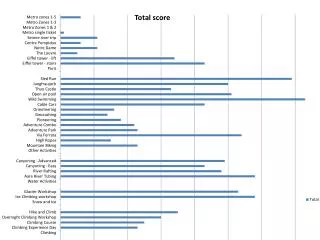
4.1 Conventional AH-64 Bearing Mass (3.17 kg) 3.9 3.7 3.5 3.3 3.1 2.9 2.7 2.5 1.0 1.2 1.4 1.6 1.8 2 • AMB design for AH-64 (Shaft OD=4.5 in) • Max Force, Fmax = 100 Lbs • Mass = 3.17 kg (Matches Existing) • Bias Current = 1.62 Amps • AMB Size, OD = 7.4 in, L = 2.2 in AMB Design AMB Mass vs Bias Current L OD Fmax = 110 Lbf • Comprehensive Radial AMB Design Code • Max force (Fmax) and current determined by material magnetic flux saturation and current density/RMS heating limitations • Based on required Fmax for given shaft OD and airgap, code optimizes AMB rotor, stator and pole geometries and coil winding parameters for minimum weight. • AMB mass similar to existing AH-64 contact hanger bearing Mass, kg Fmax = 90 Lbf Fmax = 70 Lbf Bias Current Design Level, Amps