Download
1 / 77
780 likes | 1.02k Views
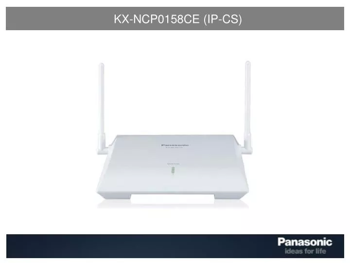
KX-NCP0158CE (IP-CS). KX-NCP0158CE (IP-CS) – Agenda. Introduction Summary Specification DSP Resource What is DECT? Installation IP-CS Configuration UPCMC Programming Site Survey Air Synchronisation Possible Installation Examples Operation LED Status VLAN.

E N D
KX-NCP0158CE (IP-CS) – Agenda • Introduction • Summary • Specification • DSP Resource • What is DECT? • Installation • IP-CS Configuration • UPCMC Programming • Site Survey • Air Synchronisation • Possible Installation Examples • Operation • LED Status • VLAN
KX-NCP0158CE (IP-CS) – Agenda (cont.) • 4. Upgrade • Firmware upgrade via FTP • PS firmware upgrade over Air • 5. Troubleshooting • FTP Server logs • UPCMC FTP
KX-NCP0158CE (IP-CS) – Summary • Wireless solution for remote office communication • PoE compatible • 8 simultaneous calls over 10/100Mb LAN • “Legacy” CS’ compatible with TDA0141 and TDA0158 • No Activation Key requirements! • Based on audio quality improvements made on TDA0158 v4.013 • LED status indication
KX-NCP0158CE (IP-CS) – Introduction Basic Specification
KX-NCP0158CE (IP-CS) – Introduction (cont.) System Capacity *1 = One TDA0158 counts as 2 x TDA0141
KX-NCP0158CE (IP-CS) – Introduction (cont.) PBX Requirements
KX-NCP0158CE (IP-CS) – Operation (cont.) DSP Resource
KX-NCP0158CE (IP-CS) – Operation (cont.) DSP Resource (cont.) Peer to peer communication is not possible IP-PT <-> IP-CS G.722 is not support on the IP-CS
KX-NCP0158CE (IP-CS) – Operation (cont.) DSP Resource (cont.) Peer to peer communication is not possible IP-PT <-> IP-CS G.722 is not support on the IP-CS
KX-NCP0158CE (IP-CS) – Operation (cont.) DSP Resource (cont.) Peer to peer communication is not possible IP-PT <-> IP-CS G.722 is not support on the IP-CS
KX-NCP0158CE (IP-CS) – Operation (cont.) DSP Resource (cont.) Max. no. of IP Trunks DSP Capacity Max. no. of Handsets Max. no. of TDM-IP Channels Outside Line Call (IP Trunk <-> Extension)
KX-NCP0158CE (IP-CS) – Operation (cont.) DSP Resource (cont.) Max. no. of IP Trunks DSP Capacity Outside Line Call (Legacy CO <-> IP-Ext) Max. no. of Handsets Max. no. of TDM-IP Channels Outside Line Call (Legacy CO <-> IP-CS)
KX-NCP0158CE (IP-CS) – Operation (cont.) DSP Resource (cont.) Max. no. of IP Trunks DSP Capacity Max. no. of Handsets Max. no. of TDM-IP Channels Extension <-> Extension Call * VoIP Channel not used for Peer to Peer mode
KX-NCP0158CE (IP-CS) – Operation (cont.) DSP Resource (cont.) Max. no. of IP Trunks DSP Capacity Max. no. of Handsets Max. no. of TDM-IP Channels IP-CS <-> Extension / IP-CS Call
KX-NCP0158CE (IP-CS) – Introduction (cont.) What is DECT? Digital Enhanced Cordless Telecommunications is an ETSI standard for digital portable phones The DECT standard specifies a means for a cordless telephone to access a fixed telecoms network via RF (radio) The radio link is terminated at the base (cell) station, which provides a gateway to the fixed network
KX-NCP0158CE (IP-CS) – Introduction (cont.) DECT RF Specification* *for reference only
KX-NCP0158CE (IP-CS) – Introduction (cont.) Available channels (TDA0158CE) 8 Voice Channels + 4 Data Channels
KX-NCP0158CE (IP-CS) – Introduction (cont.) Dynamic Channel Selection and Allocation Local RF signal strength is scanned on available channels This selection process is controlled by the Received Signal Strength Indication (RSSI) With this data, a PS is capable of choosing the optimal channel for call set-up
PS CS1 L8 CS2 L8 KX-NCP0158CE (IP-CS) – Introduction (cont.) DECT Handover This overlap allows adjacent CS’ to synchronise DECT frames and allow a PS travelling between them to handover
PS CS1 L8 CS2 L8 KX-NCP0158CE (IP-CS) – Introduction (cont.) DECT Handover (cont.) A CS will advertise its sync data to each adjacent CS via the D channels
PS CS1 L8 CS2 L8 KX-NCP0158CE (IP-CS) – Introduction (cont.) DECT Handover (cont.) For example: A PS moving from CS1 to CS2 must receive this data from both CS’ simultaneously to allow seamless handover
KX-NCP0158CE (IP-CS) – Introduction (cont.) DECT Handover (cont.) From the middle column you can see the RSSI level in relation to the CS signal Level Handover is only possible with RSSI between -65DBM and -82DBM (L10 and L3)
KX-NCP0158CE (IP-CS) – Installation IP-CS Configuration • Ensure that your PC has an IP address on the 192.168.2.x network • Select the “IP Terminal” option from the UPCMC splash menu
KX-NCP0158CE (IP-CS) – Installation (cont.) IP-CS Configuration (cont.) 3. Do not click the “Demo Mode” check box 4. Click the “Next” button
KX-NCP0158CE (IP-CS) – Installation (cont.) IP-CS Configuration (cont.) 5. Underneath the IP-CS, move DIP switch no. 7 to the ON position and click “Next” - This puts the IP-CS into “Default Mode”, and uses the IP address 192.168.2.101
KX-NCP0158CE (IP-CS) – Installation (cont.) IP-CS Configuration (cont.) 6. Plug in the IP-CS to the same network at your PC, and click Next - The UPCMC will now attempt to connect to the IP-CS via IP on the 192.168.2.x network
KX-NCP0158CE (IP-CS) – Installation (cont.) IP-CS Configuration (cont.) 7. When using DHCP, simply enter the PBX IP address and click “Next”
KX-NCP0158CE (IP-CS) – Installation (cont.) IP-CS Configuration (cont.) 8. When using static IP addresses, enter the information in the relevant boxes and click “Next”
KX-NCP0158CE (IP-CS) – Installation (cont.) IP-CS Configuration (cont.) • 9. Click to save a changes and then the “Main Screen” option. • The IP-CS will now restart. • 10. Unplug the IP-CS and return DIP switch no. 7 to the OFF position. • 11. Plug the IP-CS into the same network as your NCP
KX-NCP0158CE (IP-CS) – Installation (cont.) UPCMC Programming • Select V-IPCS4 from the list • 2. Drag the V-IPCS4 card into to Extension side of the Virtual Shelf
KX-NCP0158CE (IP-CS) – Installation (cont.) UPCMC Programming (cont.) 3. Click “Registration” 4. Select the desired port you wish to configure and click “Next”
KX-NCP0158CE (IP-CS) – Installation (cont.) UPCMC Programming (cont.) 5. The IP-CS has now been successfully registered to the NCP1000.
KX-NCP0158CE (IP-CS) – Installation (cont.) UPCMC Programming (cont.) 6. We have now named the IP-CS configured in Port 1 as “PCCUK_NCP1000_CS1” 7. The Air Sync Group has been set as Group number “1” by default
KX-NCP0158CE (IP-CS) – Installation (cont.) UPCMC Programming (cont.) 8. In Air Sync Group properties, we have named the group “PCCUK_NCP1000_CSG1”
KX-NCP0158CE (IP-CS) – Installation (cont.) UPCMC Programming (cont.) 9. In the Air Synchronisation properties, we can see that the IP-CS is successfully INS as “Sync Master CS1”
KX-NCP0158CE (IP-CS) – Installation (cont.) Site Survey If more than 1 CS is set to Radio Signal Test Mode, each CS must have a unique channel number
KX-NCP0158CE (IP-CS) – Installation (cont.) Air Synchronisation An IP-CS can have one of three CS Classes within the Air Synchronisation Group These are assigned automatically in the order they are registered to the PBX
KX-NCP0158CE (IP-CS) – Installation (cont.) Air Synchronisation (cont.) By default, this is the Air Sync classification upon IP-CS registration
KX-NCP0158CE (IP-CS) – Installation (cont.) Air Synchronisation (cont.) A Traditional (Legacy) CS will always be assigned as a CS-Master Handover is not possible between a Legacy CS-M and an IP-CS Master In the above example, the IP-CS are all configured as CS-S (slaves)
KX-NCP0158CE (IP-CS) – Installation (cont.) Air Synchronisation (cont.) A Legacy CS will receive its timing and synchronisation from the PBX, therefore TDA0141 and TDA0158 must be CS-M An IP-CS configured as CS-M will create and send out its own timing and synchronisation An IP-CS configured as CS-S will receive timing and synchronisation from either a legacy CS or IP-CS set to CS-M
KX-NCP0158CE (IP-CS) – Installation (cont.) Possible Installation Examples The legacy CS is positioned in the centre of the coverage area All IP-CS are located to allow handover to the legacy CS All IP-CS must be configured as CS-Slaves
KX-NCP0158CE (IP-CS) – Installation (cont.) Possible Installation Examples An IP-CS is positioned in the centre of the coverage area A legacy CS exists in the corner of the coverage area Handover is not possible between IP-CS M and the legacy CS
KX-NCP0158CE (IP-CS) – Installation (cont.) Possible Installation Examples An IP-CS is positioned in the centre of the coverage area Two legacy CS’ exists on the left side of the coverage area Handover is not possible between IP-CS M and the legacy CS’
KX-NCP0158CE (IP-CS) – Operation LED Status Indication OFF: Power Off or CS firmware download GREEN ON: Idle Mode – No active calls SLOW GREEN FLASHING: Active call or calls MODERATE GREEN FLASHING: All channels are busy RED ON: Fault FAST RED FLASHING: CS start up (Establishing PBX link) SLOW RED FLASHING: OUS or CS start up (Air Synch)
KX-NCP0158CE (IP-CS) – Operation (cont.) LED Status Indication (cont.) AMBER ON: Standby – Unable to complete Air Synch (with no active calls) SLOW AMBER FLASHING: Unstable Air Synch but with active call or calls FAST AMBER FLASHING: Unstable Air Synch but with all channels busy
KX-NCP0158CE (IP-CS) – Operation (cont.) VLAN There are two methods of implementing VLANS (port-based and IEEE802.1Q) IEEE802.1Q uses packet tagging to tag each packet with a VLAN ID (ingress and/or egress traffic) The IP-CS cannot recognise packets that are tagged However port-based VLAN’s should appear “invisible” to the IP-CS
KX-NCP0158CE (IP-CS) – Upgrade Firmware Upgrade via FTP Go to: - http://filezilla-project.org/ Select the “FileZilla Server” option for Windows.
KX-NCP0158CE (IP-CS) – Upgrade (cont.) Firmware Upgrade via FTP (cont.) Select the FileZilla Server executable and download
KX-NCP0158CE (IP-CS) – Upgrade (cont.) Firmware Upgrade via FTP (cont.) Run the downloaded setup executable Click “I Agree” to the License Agreement