Download
1 / 35
360 likes | 526 Views
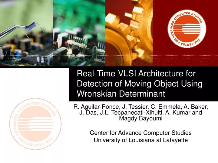
Real-Time VLSI Architecture for Detection of Moving Object Using Wronskian Determinant. R. Aguilar-Ponce, J. Tessier, C. Emmela, A. Baker, J. Das, J.L. Tecpanecatl-Xihuitl, A. Kumar and Magdy Bayoumi Center for Advance Computer Studies University of Louisiana at Lafayette. Agenda.

E N D
Real-Time VLSI Architecture for Detection of Moving Object Using Wronskian Determinant R. Aguilar-Ponce, J. Tessier, C. Emmela, A. Baker, J. Das, J.L. Tecpanecatl-Xihuitl, A. Kumar and Magdy Bayoumi Center for Advance Computer Studies University of Louisiana at Lafayette
Agenda 1. Introduction 2. Proposed Architecture 3. Results 4. Conclusion Center for Advanced Computer Studies
Background Foreground Introduction • Change detection takes one or several references frames and models the background and foreground of the image. Background Subtraction Technique • Detect: • Moving objects • Appearing objects • Disappearing objects • Discard: • Changes due to global illumination variations • Shadow cast by moving objects Center for Advanced Computer Studies
Introduction • Applications that extract high level information from raw data, i.e. video stream require accurate and robust Change Detection Systems. • Such applications include: • Video surveillance • Remote sensing • Object-based video coding • Smart cameras Center for Advanced Computer Studies
Introduction • Video Surveillance Systems must determined when an intruder has appear on the scene • Tracking of moving automobiles and persons are issues of interests on these systems. • In order to achieve these task, change detection must be performed Center for Advanced Computer Studies
Introduction • Handheld devices such as cellular phones or PDAs include acquisition, storage and/or transmission of images. In order to achieve these operations, images must be compressed. • In an Object-based Video Coding approach a scene is represented as a composition of objects, which can be independently processed and coded. • In the object-based approach, the moving objects in the video scene are extracted, and each object is represented by its shape, motion, and texture. Center for Advanced Computer Studies
Introduction • While today’s digital cameras capture images, smart cameras capture high-level descriptions of the scene and analyze what they see • A smart camera combines video sensing, high-level video processing and communication within a single embedded device. Center for Advanced Computer Studies
Goal • Change detection has been performed purely in software. • The problem of object detection, however, becomes critical in the upcoming wireless visual sensors because of size and power constraints. • The need for low-power, small size, hardware implementations is greatly felt. • This paper introduces a VLSI architecture for Wronskian Change Detector (WCD). Center for Advanced Computer Studies
Background Subtraction Techniques • The most instinctive technique is Frame Differencing followed by thresholding. • Change is detected if the difference of the corresponding pixels exceeds a preset threshold. • The advantage of this technique is its low computational complexity, however it is very susceptible to noise and illumination changes. Center for Advanced Computer Studies
Background Subtraction Techniques • Median filter is one of the most popular background subtraction techniques. • Median of each pixel of all the frames in the buffer constitutes the background estimation. • Background pixels are considered to be those that stay on more than half of the frames on the buffer. • However, this technique requires a buffer large enough to store L frames. Center for Advanced Computer Studies
Background Subtraction Techniques • Mixture of Gaussian is a recursive background technique, that recursively updates the background model based on each input frame. • This method models each background pixel by a mixture of K Gaussian distributions (K is a number between 3 and 5). • Different Gaussians are assumed to represent different colors. The probable background colors are the ones that stay longer and more static. • This technique is computationally intensive; its parameters require careful tuning and it is very sensitive to sudden changes in global illumination. Any error in the background estimation can remain for a long period due to its recursive nature Center for Advanced Computer Studies
Background Subtraction Techniques • Wronskian Change Detector employs the Wronskian of intensity ratios as a measure of change. • A large mean or large variance of the intensity ratios increases the Wronskian value. • This method can detect object interiors and structural changes. Also, WCD is robust against illumination changes. • WCD is a suitable algorithm to be implemented in real-time due to its low complexity. Also, this technique requires only one previous frame; therefore it is appropriate for applications where resources are limited Center for Advanced Computer Studies
Background Subtraction Techniques Center for Advanced Computer Studies
Background Subtraction Techniques Center for Advanced Computer Studies
Background Subtraction Techniques Frame Differencing Median Filter Wronskian Change Detector Center for Advanced Computer Studies
x1 x2 x3 x5 x6 x4 x8 x9 x7 Wronskian Change Detector • In order to determine if a change has occurred, a region of support is assigned to each pixel. • The size of the region of support can vary from 3 × 3, 5 × 5 and 9 × 9 pixels Center for Advanced Computer Studies
Wronskian Change Detector Window size 3 × 3 Window size 5 × 5 Window size 9 × 9 Center for Advanced Computer Studies
Wronskian Change Detector • Wronskian Change Detector employs the following equation • W(x/y) detects changes corresponding to dark zones, while its inverse ration W(y/x) finds if a change has occurred in bright zones. Therefore, computing both values allows robust detection against global illumination changes. • In our simulations, sizes of region of support larger than 3 do not provide better results but increases the computational complexity. Therefore a fixed value of 3 is employed in our approach. Center for Advanced Computer Studies
NTSC and PAL Standards • American Video standard, National Television System Committee (NTSC). • The NTSC standard displays 60 fields per second. Each field is composed by even and odd lines. • The NTSC signal transmits the odd fields first and then the even fields • The even and odd fields are displayed sequentially, thus interlacing the full frame. • PAL (Phase Alternation by Line) standard is the dominant television standard in Europe. • The distinction between these standards is that color is handled differently. Center for Advanced Computer Studies
x1 x1 x2 x2 x3 x3 Odd Field x5 x5 x6 x6 x4 x4 x8 x8 x9 x9 x7 x7 Even Field NTSC/PAL Odd Field Even Field Center for Advanced Computer Studies
y1 y2 y3 x2 x1 x3 x2 x10 x3 y5 y6 y4 x5 x4 x6 x5 x11 x6 y8 y9 y7 x9 x8 x12 x9 x8 x7 Wronskian Change Detector where Previous Frame Current Frame Center for Advanced Computer Studies
Frame Buffer 300 Kb Output Buffer 300 Kb Proposed Architecture • Proposed architecture is composed by three units: • Processing unit • Main Controller • Memory Unit • Decoder and encoder are used to process both standards NTSC and PAL NTSC/PAL Memory Unit Decoder Main Controller Processing Unit Pipeline Processing Element Adder Tree Queue 1 Encoder Queue 2 VGA Output Center for Advanced Computer Studies
Pipeline Processing Element • To achieve a low-power implementation a 8-bit unsigned integer arithmetic was used. • There are two main concerns: • The first one is how to capture the range of the function with only 8-bit unsigned arithmetic. • The second concern is guaranteeing precision, considering that threshold values are in the range of 0.6 to 0.7 to detect a change Center for Advanced Computer Studies
Pipeline Processing Element • The PE must be designed to capture the range of D(xi,yi) that could indicate a change. • Therefore, the equation must be scaled so that an unsigned 8-bit integer threshold can be used and all overflows are saturated. • Only the partial range of D(xi,yi) where THmin ≤ D(xi,yi) ≤ nTHmax is significant, where THmin and THmax are the minimum and maximum threshold to be used Center for Advanced Computer Studies
D(x,y) Latch 8-bit Division 1st stage Latch Division (2nd stage) and subtraction Latch 8-Bit Multiplication First stage Latch Multiplication (2nd stage) Latch x y Pipeline Processing Element • This solved the problem of precision, but creates results that are too large to add n times. • For that reason, the five least significant bit of the product are discarded after multiplication, and the rest of the bits are employed as the result Center for Advanced Computer Studies
Pipeline Processing Element • The implementation of the system is done with a fixed region of support size of 3 × 3. • The main components of the PE are divider, adder and multiplier. • Multiplication is done by Booth algorithm because it represents a good trade-off between speed and power for 8 bit fixed point arithmetic • Integer division using 8 conditional subtractors is simple and fast enough for our application • The architecture is capable of analyze frame size of 640 × 480 pixels Center for Advanced Computer Studies
Processing Unit Pipeline Processing Element Adder Tree Queue 1 Queue 2 Processing Unit • The design uses control signals to pad the image by grounding the bus whenever it is required. • The adder trees sum PE outputs to produce the final results. • These results are compared to the threshold, and the change/no change bits are then stored into the output frame Center for Advanced Computer Studies
Main Controller • The system is managed by the control unit. The controller has three states: • Process, the system input and calculates Wronskian value • Display shows the output through the encoder • Idle, the process unit does not performed any action • The maximum frame rate is 15 frames per second. If the application require less than 15 fps, the system will remain idle for the rest of the frames of a second Center for Advanced Computer Studies
Memory Unit • For storing the preceding frame data, we used a 300Kb memory. • Another memory of same size is required to store the output values. T • The memory is addressed by 19 bits that includes field index for a frame, vertical addressing and horizontal addressing. • The values for 2-pixels, i.e., 16 bits of data is read and stored at a time. Center for Advanced Computer Studies
Implementation • Implementation of the proposed architecture was done in VHDL using Mentor Graphic Modelsim Simulator. • Synthesis was done using Synopsis Synthesis Tools targeting Xilinx Virtex II XCV800 FPGA. • The XSV-800 board can accept PAL, SECAM, or NTSC video with up to 9-bits of resolution on the red, green, and blue channels and can output video images through a 110 MHz, 24-bit digital to analog converter. • Two independent banks of 512K x 16 SRAM are provided for local buffering of signals and data Center for Advanced Computer Studies
Simulation Results Center for Advanced Computer Studies
Simulation Results • Most of the area and power consumption is occupied by the processing unit. • The adder tree is fully asynchronous and its maximum delay of critical path is 12 ns. • The PE is synchronous with four stages of asynchronous logic. • One stage's maximum delay of critical path is 27 ns. • The total power consumption of the system is 121 mW. The total area of the system in LUT is 2312 (7247 slices). Center for Advanced Computer Studies
Conclusion • A background subtraction architecture using the Wronskian Change Detector algorithm has been presented for VLSI realization in wireless visual applications. • The proposed architecture consists of three units: processing, memory and controller. • The processing unit is composed by pipeline processing element that performs the basic operation. Center for Advanced Computer Studies
Conclusion • Partial results are stored and used on the adder tree to obtain final results. • Memory unit consists of two buffers, one stored the previous frame (Frame Buffer) and the other stored partial results and output. • The architecture is capable of computing Wronskian, Conjugate Wronskian and both. • The maximum frame rate is 15 fps. The power dissipated by the whole system is 121 mW. The total area of the system in LUT is 2312. Center for Advanced Computer Studies
Thank you Center for Advanced Computer Studies