Download

1 / 15
160 likes | 278 Views
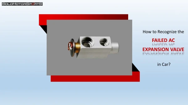
EXPANSION VALVE SYSTEM. 1. Purge gauge lines. Connect service gauge manifold to base-valve service ports. Run system at least 10 minutes to allow pressure to stabilize.

E N D
EXPANSION VALVE SYSTEM • 1. Purge gauge lines. Connect service gauge manifold to base-valve service ports. Run system at least 10 minutes to allow pressure to stabilize. • 2. Temporarily install thermometer on liquid (small) line near liquid line service valve with adequate contact and insulate for best possible reading. • 3. Check subcooling and superheat. Systems with TXV application should have a subcooling and superheat of 9 ±3 ºF. • a. If subcooling and superheat are low, adjust TXV to 9 ± 3ºF then check subcooling. • b. If subcooling is low and superheat is high, add charge to raise subcooling to 9 ± 3ºF then check superheat. • c. If subcooling and superheat are high, adjust TXV valve to 9 ± 3ºF then check subcooling. • d. If subcooling is high and superheat is low, adjust TXV valve to 9 ± 3ºF superheat and remove chargeto lower the subcooling to 9 ± 3ºF. • NOTE: Do NOT adjust the charge based on suction pressure unless there is a gross undercharge. • 4. Disconnect manifold set, installation is complete. • Subcooling Formula = Sat. Liquid Temp. - Liquid Line Temp.
SUPERHEAT METHOD THE SUPERHEAT METHOD IS USED FOR SYSTEMS USING A FIXED ORIFICE TYPE METERING DEVICE Orifice Metering Device
USING SUPERHEAT CALCULATOR • GET THE RETURN WET BULB TEMPERATURE AT THE RETURN AIR GRILL USING A SLING PSYCHROMETER OR METER CAPABLE OF READING WET BULB TEMPERTURE • GET THE OUTSIDE AMBIENT TEMPERATURE IN THE SHADE OF THE CONDENSING UNIT • SET ARROW TO INDOOR ENTERING AIR WET BULB TEMPERATURE • LOCATE CONDENSER ENTERING AIR DRY BULB TEMPERATURE • READ REQUIRED SUPERHEAT TEMPERATURE AT CONDENSER ENTERING AIR DRY BULB TEMPERATURE • ADD CHARGE TO LOWER SUPER HEAT • REMOVE CHARGE TO RAISE SUPERHEAT
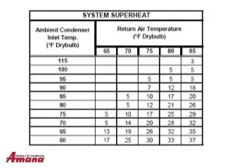
USING SUPERHEAT TABLE • GET THE OUTSIDE AMBIENT TEMPERATURE IN THE SHADE OF THE CONDENSING UNIT • GET THE RETURN DRY BULB TEMPERATURE AT THE RETURN AIR GRILL • INTERSECT THE 2 NUMBERS • THAT WILL GIVE YOU THE AMOUNT OF SUPERHEAT YOU NEED
Super-heat and Sub-cooling charts • The super-heat and sub-cooling charts will be posted on the back side of the control door.
EXAMPLE • AMBIENT OUTSIDE TEMPERATURE (IN THE SHADE OF THE CONDENSOR) IS 95 DEGRESS • RETURN AIR (DRY BULB) IS 75 DEGREES • INTERSECT THE 2 NUMBERS AND YOUR SUPER HEAT WILL BE 5 DEGREE
INSTALL THERMOMETER • INSTALL ON THE SUCTION LINE ( LARGER LINE ) • INSULATE THE PROBE FOR AN MORE ACCURATE READING
READING THE SATURATED EVAPORATER TEMPERTURE • ON THE LOW SIDE OF YOUR COMPOUND GAUGES ( BLUE ) • THE OUTSIDE READING IS YOUR PRESSURE • THE INSIDE (R 22) IS YOUR SATURATED EVAPORIZING TEMPERTURE
EXAMPLE • YOUR LOW SIDE PRESSURE IS 75 PSI • DIRECTLY BELOW THAT NUMBER IS THE SATURATED EVAPORIZING TEMPERATURE, WHICH IS 44 DEGREES • TAKE YOU SUCTION LINE TEMPERTURE, WHICH IS 65 DEGREE
EXAMPLE • SUBTRACT THE 2 NUMBERS AND THAT HOW MUCH SUPEREHEAT YOU HAVE • 65 - 44 =21 SUPERHEAT • WE ONLY NEEDED 5 DEGREES • ADD CHARGE TO LOWER SUPER HEAT • REMOVE CHARGE TO RAISE SUPERHEAT
Charging Two Stage Units • Set unit to operate at low stage cooling. • Operate for 10 minutes. • Check and record low stage liquid pressure at the service valve. • Set thermostat to operate at high stage. • Operate for 10 minutes. • Check and record high stage liquid pressure at service valve.
Charging Two Stage Units • The high stage pressure should be noticeably higher than the low stage liquid pressure. • If the pressures are identical, the compressor did not switch from low to high stage. • Verify wiring and t-stat settings. • Run the unit on low stage and make the final charge adjustments on low stage. • Do not adjust charge to change sub-cooling on high stage. Charge adjustments must only be made under low stage cooling.