Download
1 / 35
390 likes | 721 Views
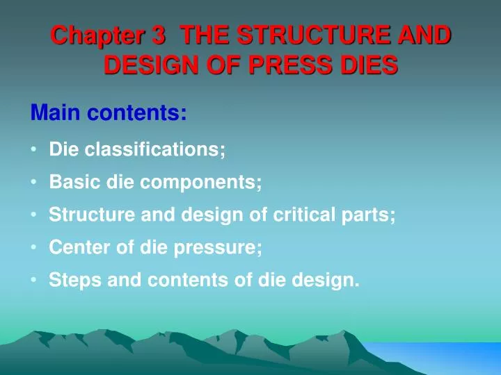
Chapter 3 THE STRUCTURE AND DESIGN OF PRESS DIES. Main contents: Die classifications; Basic die components; Structure and design of critical parts; Center of die pressure; Steps and contents of die design. Key point. Classification of dies Structure and design of critical parts

E N D
Chapter 3 THE STRUCTURE AND DESIGN OF PRESS DIES Main contents: • Die classifications; • Basic die components; • Structure and design of critical parts; • Center of die pressure; • Steps and contents of die design.
Key point • Classification of dies • Structure and design of critical parts • Center of die pressure • Grammar:the use of prepositions
New words simple/plain die 简单模;die block 凹模块 compound/combination die 复合模 Progressive die 连续模/级进模;punch 凸模 die set 模架;die shoe下模座;guide plate 导板 shank holder上模座;punch holder 凸模固定板 guide rails导尺;stripper 卸料板;pilot 导正销 guide post/bushing 导柱/导套;screw 螺钉/栓 knock-out 顶件块/推件块;dowel 销钉 backing plate 垫板;blank holder承料板
§3.1 Typical structures and their characteristics of press dies 1. Die Classifications 1.1 Manufacturing processes 1.2 Number of operations 1.3 Number of stations 1.4 Die structure 1.5 Die material 1.6 Production quantities of pieces 2. Basic die components 2.1 Technological components 2.2 The structural components
1. Die Classifications 1.1 Manufacturing processes blanking dies, punching dies, bending dies, drawing dies, et al. 1.2 Number of operations single-operation dies----simple/plain dies multi-operation dies----combination/compound dies ----progressive dies
1. Die Classifications 1.3 Number of stations Single station dies Multi-station dies----progressive dies Single station diesmay be : Combination(a die in which both cutting and noncutting operations are accomplished at one press stroke) or Compound (a die in which two or more cutting operations are accomplished at every press stroke).
1. Die Classifications Progressive diesare made with two or more stations. Each station performs an operation on the workpiece or provides an idler station(空位) so that the workpiece is completed when the last operation has been accomplished. After the first part has traveled through all the stations, each subsequent strokes(冲击)of the press produces another finished part. What’s different and common features between progressive dies and compound dies?
1. Die Classifications 1.4 Die structure Guiding(导向及导料): plain, with guide plate, with guide posts ; stock guide, guide rails, guide pins (elastic and solid), pilots Stripper:movable elastic and solid Stop pin(挡料):solid and elastic, finger stops(始用挡料销), adjustable and fixed
1. Die Classifications 1.5 Die material carbide(硬质合金),rubber, polyester(聚酯), polyurethane(聚胺酯), zinc alloy, etc 1.6 Production quantities of pieces Class A—high, best of materials Class B—medium, cheaper materials, die cost Class C—low-volume, cheapest Temporary dies—small, lowest cost
2. Basic die components 2.1 Technological components Directly participate in forming the work piece and have direct contact with a material. Punches, die block, form block,guide rails, stripper, drawing die,blank holder 2.2 The structural components Securely fasten all components to the subset and die set. punch holder, die shoe,shank,guideposts,guide post bushings, springs, screws , dowels
2. Basic die components 1 -shank 2 -shank holder 3 -backing plate 4 -punch holder 5 -punch 9 -guide rail 10-die block 11-die shoe 13-guide plate Die with guide plate
2. Basic die components 1 -shank 2 -shank holder 3 -backing plate 4 -punch holder 5 -punch 6 -guide post bushing 7 -guide post 8 -stripper 9 -guide rail 10-die block 11-die shoe Die with guide post and guide post bushing
§3.2 Structure and design of critical parts 1. Introduction 2. Die blocks 3. Punches 4. Stripper plates 5. Die components for guiding and stopping
1. Introduction • A blanking die Cheaper to make and faster in operation • return-blank die:sheared blank returns upword • drop-blank die • A punching die May be manually or automatically fed
2. Die blocks • Construction component housing the opening and receiving punches. 2.1 die opening profile 2.2 fastening to the die shoe 2.3 sectioned die 2.4 calculation of die block dimensions
2. Die blocks 2.1 die opening profile a) gives the highest quality workpiece, the most expensive. blanking parts having complex contours with greater accuracy. b) making small parts with low accuracy. c) the simplest,making relatively large parts. d) to punch small-diame ter (d < 5 mm) holes.
2. Die blocks a) 2.2 fastening to the die shoe a) socket head screws are inserted from the bottom of the die shoe into threaded holes in the die block.Dowels are used to prevent a shift in the position of the block. b) held in the retainer (has a shoulder) c) pressed into the retainer (has no shoulder) d) fastened into the retainer with a ball and screw e) a bushing is used at the bottom
2. Die blocks 2.3 sectioned die workpiece- large, die opening - complicated, contours - difficult to machine
2. Die blocks 2.4 calculation of die block dimensions A=a+2e, B=b+2e. Rectangular: Circular:
3. Punches Main consideration when design: • do not buckle; • be strong enough to withstand the stripping force; • not be able to rotate as a result of the cutting action. 3.1 punch face geometry 3.2 methods for assembling punches 3.3 punch calculations
3. Punches 3.1 punch face geometry • Flat punch-double bevel die • Concave punch-flat die • Bevel punch-flat die • Flat punch-concave die a) flat,b) concave,c)bevel, d) double bevel
3. Punches 3.2 methods for assembling punches Backing plate:P=F/A>Pd 3.3 punch calculations • Compression stress: • Buckling calculation:
4. Stripper plates • Solid stripper The force of the press is used for stripping operation. • Elastic stripper Usage:very accurate, thin material, thin punches. How: hold the scrap strip in a flat position before the punch makes contact with the workpiece.
5. Die components for guiding and stopping The group ofdie components known as guides and stops includes the following components: 5.1 Stock guide and guide rails 5.2 Die stops and french notch punch 5.3 Positioning the individual blank 5.4 Pilots
5. Die components for guiding and stopping 5.1 Stock guide and guide rails Guide rails: Used to guide the work strip through the die. Be placed between the stock shelf of die block and the stripper plate or guide plate. Types: solid and elastic
5. Die components for guiding and stopping 5.2 Die stops and french notch punch Die stops: Used to stop the material strip after each feed movement is completed. French notch punch: Used for trimming away a length of work strip that is equal to the progression of the die. Finger stops: Used to stop new strips in the proper location in a die.
5. Die components for guiding and stopping 5.3 Positioning the individual blank • Three dowels • A ring • A combination of dowels and guide-rails
5. Die components for guiding and stopping 5.3 Pilots Used in progressive and compound dies to position the work strip so that the relationships between stations or previously punched holes and the outside blanked contours of work pieces may be maintained.
§3.3 Steps and contents of die design 1. Technological property analysis 2. Center of die pressure 3. Close height 4. General procedure Homework: 3 supplements on center calculation of die pressure.
1. Technological property analysis • Structure of work-piece • Dimensional tolerance(尺寸公差), geometrical tolerance(形位公差), and surface roughness(表面粗糙度) • Dimension base
2. Center of die pressure The die pressure should be centered on a vertical line passing through the specific point that defines the resultant force of the punching and blanking forces. • Mathematical solution X,Y=coordinates of the center • of the die pressure xi,yi=coordinates of the center of gravity of a partial length of cut edge Li=partial length of cut edges
2. Center of die pressure • Graphical solution Use the force polygon and link polygon closed to determine the main forces LRx and LRy operating in any two directions (preferably at right angles). The point of intersection of the lines of application will indicate the position of the center of die pressure.
ram frame plate 3. Close height
4. General procedure 4.1 According to the technique analysis , select die type and determine die structure • structure of die----simple, compound, combination, et al. • operation way----manual, automatic or self-automatic • removal of blanks or scraps • stripper----elastic or solid • accuracy of die 4.2 Center of die pressure Calculation/determination 4.3 Close height 4.4 Draw up the technological plan