Download
1 / 79
790 likes | 900 Views
Characterization of Unpaved Road Conditions through the Use of Remote Sensing RITARS-11-H-MTU1 Project Update – 1/11/2013. Colin N. Brooks, Michigan Tech Research Institute (MTRI ) Dr . Tim Colling , Michigan Tech Center for Technology and Training (CTT) Christopher Roussi , MTRI

E N D
Characterization of Unpaved Road Conditions through the Use of Remote SensingRITARS-11-H-MTU1 Project Update – 1/11/2013 Colin N. Brooks, Michigan Tech Research Institute (MTRI) Dr. Tim Colling, Michigan Tech Center for Technology and Training (CTT) Christopher Roussi, MTRI Caesar Singh, P.E., US Department of Transportation Research & Innovative Technology Administration (RITA) www.mtri.org/unpaved
Characterization of Unpaved Road Conditions through the Use of Remote Sensing Goal of the Project: Extend available Commercial Remote Sensing & Spatial Information (CRS&SI) tools to enhance & develop an unpaved road assessment system by developing a sensor for, & demonstrating the utility of remote sensing platform(s) for unpaved road assessment. • Commercially viable in that it can measure inventory and distress data at a rate and cost competitive with traditional methods • Rapid ID & characterization of unpaved roads • Inventory level with meaningful metrics • Develop a sensor for, & demonstrate the utility of remote sensing platform(s) for unpaved road assessment • Platform could be a typical manned fixed-wing aircraft, UAV, or both; depends on relative strengths & weaknesses in meeting user community requirements • Simplify mission planning, control of sensor system, & data processing fitting for a commercial entity or large transportation agency • Demonstrate prototype system(s) to stakeholders for potential implementation developed through best engineering practices • Develop a decision support system to aid the user in resource management and planning
Project web pagehttp://www.mtri.org/unpaved • Posting deliverables once approved by sponsor – 5-A (Platforms) and 6-B (DSS example) posted Nov. 5, 2012
Project Partners Partners: • Michigan Tech Center for Technology & Training: Gravel roads & Decision Support Tool software expertise • Transportation Asset Management Council of Michigan (TAMC) – shared PASER data, provide advice (briefed 1/9/13 on progress, pleased with results • SEMCOG (Southeastern Michigan Council of Governments) – shared aerial imagery, provide advice, inventory needs • RCOC (Road Commission for Oakland County) – provide advice, local expertise on unpaved roads management needs • USDOT-RITA – Program Manager, advice, transportation expertise • Michigan Tech Research Institute (MTRI) – project lead, remote sensing, engineering, UAVs, software coding, image processing
Project Review Briefing, Part 1-A: Current Status of Project Work January 11, 2013
Task 1- Requirements Definition • We need to understanding the types of distresses (road features) we need to sense, and to what precision & accuracy we need to measure them to able to produce useful information to understand unpaved road condition • We also need to understand where the unpaved roads are, how many miles there are! Inventory is important • Distress types: • Cross section (loss of crown) • Drainage • Washboarding (corrugation) • Potholes • Ruts • Float aggregate • Dust (not part of this project; different sensor/platform)
Road Characteristics • Unpaved roads have common characteristics • Surface type • Surface width • Collected every 10', with a precision of +/- 4” • Cross Section (Loss of Crown) • Facilitates drainage, typically 2% - 4% (up to 6%) vertical change, sloping away from the centerline to the edge • Measure the profile every 10' along the road direction, able to detect a 1% change across a 9'-wide lane • Potholes • <1', 1'-2', 2'-3', >3‘ width bins • <2”, 2”-4”, >4” depth bins • Ruts • Detect features >5”, >10' in length, precision +/-2” • Corrugations (washboarding) • Classify by depth to a precision of +/-1” • <1”, 1”-3”, >3” • Report total area of the reporting segment affected • Roadside Drainage • System should be able to measure ditch bottom relative to road surface within +/-2”, if >6” • Detect the presence of water, elevation +/-2”, width +/-4” • Float aggregate (berms)
Derived Requirements = feasible system • Flight Geometry • From the “easy to deploy”, we infer that the platform will not be flying above FAA-imposed limits of 400ft (for a UAV). If a manned platform, flight-plans will need to be filed, with flights at the lowest safe altitude • Sensor Field-of-view (FOV) • From the size of the road and ditches, and the altitude, we infer that the FOV must be 2x the road width or 72'. This corresponds to a focal length of 75mm • Resolution • From distress features, the smallest size needed is 1”. For a 75mm lens with a FOV of 72', and applying the Nyquist Sampling criteria, one would have to have 1728 pixels across the road to measure +/-1”, and would correspond to a sensor of about 4Mpixels • Image Capture Speed • Worst case is a manned platform flying just above stall-speed. Along-track FOV is 94'; for 50% overlap in consecutive images, at 75mph, one must collect images at 2.25 frames per second. • Other potential requirements to be determined as project develops • Based on illumination, reflectivity, etc. to be measured later
Del. 2-A State of the Practice • Reviews several assessment methods: Visual, Combined (Visual + Direct), Indirect Data Acquisition; will be covered later today • Visual methods include: • Unimproved PASER & Gravel PASER • Road Surface Management System • Standard Visual Assessment Manual for Unsealed Roads, TMH12 • Central Federal Lands, Highway Division - Subjective Rating System • Combination methods include: • Central Federal Lands, Highway Division - Objective Rating System • Unsurfaced Road Condition Index (URCI) – Department of the Army • Indirect data acquisition methods include: • Ground Penetrating Radar • Remote Sensing – Unmanned Aerial Vehicle (UAV) (Dr. C. Zhang, SDSU) • Survey – Ultralight Aircraft • Road Roughness Using Accelerometer Technology by Opti-Grade®
Combined Methods: Dept. ArmyUnsurfaced Road Condition Index • Representative Sample Segment (approx. . 100’ long) 2 Part Rating System (per distress) • Density • Percentage of the sample area • Severity • Low • Medium • High
Combined Methods: Dept. ArmyUnsurfaced Road Condition Index Decision matrix from distress criteria (Eaton 1987a)
Del. 3-A: Remote Sensing the Phenomena of Unpaved Road Conditions • Motivation for Phenomenology Approach: Understand how the physical properties of the road surface distresses manifest themselves in observable ways • Color (inc. need for balancing) • Texture • Patterns • profile (inc. 3D structure) • Polarization • Only then can appropriate processing tools be chosen, tailored to the observable phenomena • Also informs sensor selection • Color correction enables better image comparison – gray card used
Del. 4-A: Sensor Selection for use in Remote Sensing the Phenomena of Unpaved Road Condition • Needs to meet sensor requirements (FOV, focal length, resolution, frame-rate) • CCD vs. CMOS sensor types – not important differences for this program • Need remote control • Mid-level sensor • Grey – no remote; older cameras – red
Selected sensor: Nikon D800 • Nikon D800 – full-sized (FX) sensor, 36.3 Mp, 4 fps - $3,000 • More than meets all our requirements • Weight prime lens, weights ~1.5 kg
Lenses: candidate & selected • Need to minimize motion blur – fast shutter speed • At 400’, ground-sample spacing of ½” = scene size of 200’, lens focal length = 90 mm; at 100’, 44mm lens; 40-90 mm range • Selected Nikon AF-S 50mm f/1.4 ($480) lens – meets reqs.
Del. 6-A: A Demonstration Mission Planning System for use in Remote Sensing the Phenomena of Unpaved Road Conditions • Describes process of planning a data collection mission: • Where are the unpaved roads? (inventory) • Possible obstacles to flight operations • Creating a flight trajectory • Likely to need to be updated as program develops • Planner – needs to display where unpaved roads are, conditions (if known) from last inspection, date, date/type of remediation, public input/comments
Flight Safety & Effectiveness Inspection • Evaluate site for safe flight operations, suitable for aerial collection • High-voltage towers, restricted airspace, visual obstructions • Manned vs. unmanned: • Manned: licensed pilot review, FAA regs followed, safety margins included • Unmanned: more possible instructions
Flight trajectory planning • Ground Station Control program / tool – create flight trajectory • Includes ability to automatically take off, fly, auto-land; operator has joystick control at all times • Includes Google Earth / Maps information Typical view of opening screen in Ground Station program
Ground Station Control tool • User creates series of waypoints, flight parameters (altitude, speed) • Waypoints – can include altitude, loiter, speed to next point, type of turn • Can see estimated time, distance; view from any angle, altitude • Flight plan is loaded into autopilot, mission can begin Editing session to plan mission along an unpaved road Complete flight path, looking down
Inventory: Surface Type and Widthneeded for mission planning • How many miles of unpaved road are there? • Need to able to determine this inventory • c. 43,000 (1984 estimate) – but no up-to-date, accurate inventory exists • c. 800 miles in Oakland County • We can extract this from recent, high-resolution aerial imagery (part of Task 6)
Methodology • SEMCOG images were mosaicked into 2x2 squares • Principal Component Analysis (PCA) was performed on each mosaic. This assists with the detection of shadowed areas. • Using Trimble’s eCognition, mosaics are segmented by object-based image analysis. This attempts to group pixels by spectral similarities. • eCognition then classified the resulting objects based on a set of rules that account for different spectral characteristics.
ROC Curve Analysis • A Receiver Operating Characteristic (ROC) curve was performed to find the optimal threshold for the greatest contributing factor to the detection of unpaved roads; The IR-Green parameter. • An ROC curve shows the fraction of true positives out of the positives (ρd) plotted against the fraction of false positives out of the negatives (ρfa). TP = Road pixel detected as road FN = Road pixel detected as not road FP = Not road pixel detected as road TN = Not road pixel detected as not road
ROC Curve Analysis, cont. • This allows us to find the best value for IR-Green by selecting a value that maximizes ρd where ρfa is at the lowest.
Methodology, cont. • The resulting objects classified as unpaved road were then exported to ArcGIS as polygon shapefiles. • The unpaved road polygons were then merged to one large polygon • Here our methods finding the unpaved roads diverged into two paths. • The large polygon was intersected with the Michigan State Framework Roads layer, resulting in lines that only exist within the eCognition output. The length of these lines were compared to the length of the Framework Roads to find a percentage of coverage. • The large polygon was unioned with a 30-foot buffer of the Framework Roads layer. This allowed us to find the area of individual polygon segments in relation to the roads they cover. From here we can take the area of the road segment buffers and compare them to the area of polygon segments and derive a percentage of coverage.
Results • Using the first method works well when road centerlines are, in fact, at the center of the road; However, this is not always the case. • Using the second method yields much better results when the centerline is shifted to one side or off the road entirely.
Results • Roads in treeless areas (e.g. croplands) are found easily and reliably
Results • Roads detection in wooded areas where trees cover the roads are also found reliably
Mapped northern Oakland Co, MI using unpaved roads methodology • As of the end of 2012: Mapped 1088.1 miles of unpaved roads out of 3087.2 miles assessed for Oakland Co. (Paved = 1999.1 miles) • Started on Monroe County
Monroe County, MI • Monroe Co MI selected for processing – different land use • Fewer roads, more rural/agricultural, most roads easily visible from the air • Road network processed using same methodology as Oakland County • 658 miles (1060 km) or 40% of the county road network processed so far • 372 miles (599 km) 56% of processed roads were classified as unpaved. • Processing continues…
Monroe County Unpaved Roads 372 miles (599 km) of 658 miles (1060 km) of roads processed (56%) were classified as unpaved. 40 percent of the county road network has been processed so far.
Monroe County Road segmentation • Road segments classified by eCognition • red = unpaved, green = vegetation, cyan = shadow, lt green = bare earth
Monroe County road classification • Segments classified as unpaved (red) with road network overlay in ArcGIS • The N-S road at right (east) side of image correctly classified as paved, all other roads unpaved.
Monroe County • Quality of road centerline data important • Poor centerline alignment with image can cause misclassification • Road segment classified unpaved even though road is paved
Del. 5-A: Candidate and Recommended Remote Sensing Platforms for Unpaved Road Condition Asessment Report Two platforms required to carry sensor are being evaluated in this project: UAS (UAV) Fixed-wing manned Factors affecting choice are Size, weight, and power (SWAP) requirements Range, altitude, and speed requirements Reliability Cost
UAS-specific factors FAA rules prohibit unmanned flight in the national air-space Must stay below 400ft Must remain in sight at all times At that altitude, forward speed must be low, to be able to image with the required scene overlap at the maximum rate of the sensor Low speed → rotary wing aircraft, since fixed-wing would stall Must be able to loft 5kg of sensor, controller, and batteries Must be able to fly for 20min under full load, in sight of safety pilot
UAS Choice2 Rotomotion >$30k Platform made in France, and parts come from there Had prior (bad) experience with this company Viking >$50k Platform made and serviced in Oregon Good interactions and company reviews Bergen (both models) <20k for two platforms, one with autopilot, one without Made and serviced in Michigan Excellent customer service and product reviews Did not need e-observer gimbaled camera-mount Chose the Tazer800 Considering adding a hexacopter – smaller payload but simpler to fly
Fixed-wing Choice FAA restrictions on fixed-wing flight >500ft altitude Sensor cannot be attached to aircraft without FAA review Any small aircraft meet SWAP and flight requirements Charter costs vary by region, but generally range from $1600-$2500/hr Would have to fly to site, collect data, and fly back Specific models not yet identified Will select in the next quarter
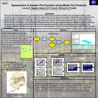
UAV & Airborne Data Collection for Unpaved Road Condition Assessment –November, 2012 preliminary data collections
UAV Collects • Total flight time: 16 minutes (not including a 2 minute reserve) • Flight time for a 200 m section: 4 minutes • During collects helicopter is flown at 2 m/s and at an altitude of 25 m and 30 m • Lens Used: 55 mm prime lens Example flight at http://www.youtube.com/watch?v=KBNQzM7xGQo
Ground data being collected for all roads being flown for assessment
Aerial Collect • Aircraft: Cessna 172 • Average air speed: 65 Knots (~75 mph) • Altitudes flown: 500 and 1000 feet • Lens Used: 105 mm prime lens