Download
1 / 23
230 likes | 329 Views
New THGEM test in the COMPASS hall. Preparation of the test Preliminary check with Fe source The LED light sources The test area in the COMPASS hall Measurements with analog r/o Measurements with digital r/o. Motivations for this test. From:

E N D
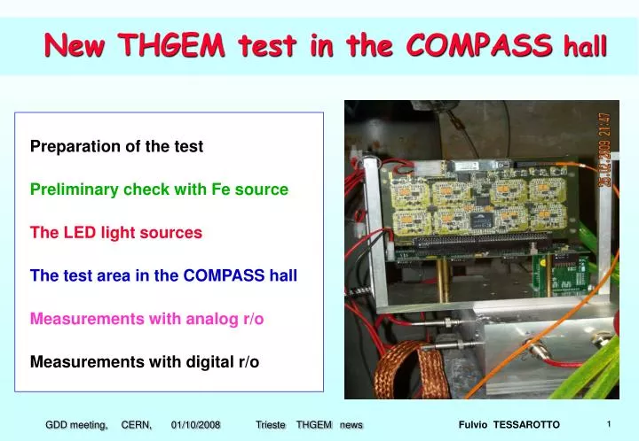
New THGEM test in the COMPASS hall Preparation of the test Preliminary check with Fe source The LED light sources The test area in the COMPASS hall Measurements with analog r/o Measurements with digital r/o Fulvio TESSAROTTO
Motivations for this test From: • CsI photoelectron extraction and backscattering measurements • first indications from simulation of fields and trajectories • THGEM performances with different gases • we concluded that a methane based gas mixture is needed We experienced difficulties in reaching high gains without sparks • Decision to build a quadruple THGEM • Test it with light source • Obtain authorization to use flammable gas • Try to characterize the time response The COMPASS RICH test area seemed to be the easiest choice Fulvio TESSAROTTO
Preparation of the test Design and build a new chamber with: - 9 HV connectors and 2 gas connectors, • - anode segmented in 16 pads, • - a fused silica window (Heraus Suprasil II) • - a flange for light source mounting Design and build mechanics for: - testing the LED light source behavior - interfacing the light source to the chamber Find low wavelength LED and best possible driver Most important: involve many COMPASS colleagues for the test Fulvio TESSAROTTO
Choice of THGEM “Standard geometry”: - Thickness = 0.4 mm • - Hole diameter = 0.4 mm • - Pitch = 0.8 mm • - Rim = 10 μm Production: - Laser + etching - First set from ELTOS Second best after “global etching” Fulvio TESSAROTTO
drift THGEM 1 CsI THGEM 2 2.0 mm THGEM 3 2.0 mm Etransfer THGEM 4 2.0 mm Einduction 2.0 mm anode The chamber Fulvio TESSAROTTO
First test: triple THGEM, Ar-CH4 50-50 55Fe source: rate ~ 200 Hz, primaries: ~ 200 THGEM: 30x30;0.4, 0.4, 0.8, 10 μm Spacings: 2.0 mm (drift sp. = 4.0 mm) Fields: Drift = Induction = 1.5 kV/cm Transf.1 = Trasnf.2 = 1.0 kV/cm THGEM voltages: ΔV2 = ΔV3 = 1400 V largest gain with 55Fe source so far ΔV1 (V) Fulvio TESSAROTTO
Very interesting currents: First test: triple THGEM, Ar-CH4 50-50 55Fe source: rate ~ 200 Hz, primaries: ~ 200 THGEM: 30x30;0.4, 0.4, 0.8, 10 μm Spacings: 2.0 mm (drift sp. = 4.0 mm) Drift: + 160 pA Top1: + 30 pA Bottom1: 0 pA Top2: + 110 pA Bottom2: - 50 pA Top3 : + 710 pA Bottom3: - 610 pA Anode: - 340 pA Fields: Drift = Induction = 1.5 kV/cm Transf.1 = Trasnf.2 = 1.0 kV/cm THGEM voltages: ΔV2 = ΔV3 = 1400 V Fulvio TESSAROTTO
CsI deposited on one half only 8 pads corresponding to the CsI coated half CsI deposited by Miranda Van Stenis (A. Braem’s lab.) on 17/02/2009 8 pads corresponding to the uncoated half CsI coated half uncoated half Fulvio TESSAROTTO
We bought 2 LED’s of 255 nm from “Laser 2000” company, Paris Fulvio TESSAROTTO
First test of “255 nm LED” Check that the LED is properly working (no specifications available) - power DC mode direct/inverse and check current • - try to see glow from UV light on fluorescent liquid • - characterize the LED emission spectra • - estimate and tune the LED light output in pulsed mode with PM We then mounted it on the chamber with CsI coated THGEM: - no measurable photocurrent seen - with multiplication both signals and currents are seen Conclusion: we can use it for the test Colleagues from Freiburg bought a “270 nm LED” able to provide pulses of 600 ns length, up to 40 MHz Fulvio TESSAROTTO
Mechanics for the LED LED quartz window THGEM Fulvio TESSAROTTO
Study of the LED with a MAPMT LED 50 μm pin-hole quartz window THGEM MAPMT Fulvio TESSAROTTO
Emission spectra for LED “255” nm and “270” nm Using an Avantes spectrophotometer we measured the emission spectra for both “255 LED” and “270 laser LED” Both seem to emit in a region where CsI has extremely low Q.E., if any. Fulvio TESSAROTTO
COMPASS RICH THGEM TEST AREA Gas Distribution rack Power plugs THGEM Detectors Methane Detection Head Methane Leaks Collector Bottle of Ar/CH4 50/50 Bottle of Ar/CO2 70/30 Safety box for radioactive sources Electronics Racks Emergency Button Sliding door We have been authorized to use flammable gas: Ar-CH4 50-50 or pure CH4 for two weeks, after some interactions with the safety officers and filling of a finite number of safety papers. Fulvio TESSAROTTO
Amplitude spectra with “255 nm LED” “255 nm” LED continuous current: Voltages: 7150 7150 5525 5325 3775 3575 2150 1950 620 For high rates the analog r/o piles up the signals; lowering the rate we reach a minimum slope and lowering it further the event rate changes without changes in the slope of the spectra => single photon Fulvio TESSAROTTO
Amplitude spectra from pulsed LED Pulsed LED provides single photoelectrons with probability between 0.1% and 1% Voltages: 7150 7150 5525 5325 3775 3575 2150 1950 620 Fulvio TESSAROTTO
Estimate of the gain: ~ 100,000 The chamber was very stable in these conditions Fulvio TESSAROTTO
Amplitude spectra with “Freiburg LED” Random pulses – high frequency Fixed frequency: 9kHz Voltages: 7100 7100 5500 5300 3750 3550 2150 1950 620 Fulvio TESSAROTTO
Using FREIBURG pulsed LED: Voltages: 7100 7100 5500 5300 3750 3550 2150 1950 620 Fulvio TESSAROTTO
Delta V1 increased by 30V Fulvio TESSAROTTO
Zooming the low amplitude part Saturation of Amplifier Changing the GAIN of the Amplifier There is no clear evidence of “Polya” shape Fulvio TESSAROTTO
First look at timing properties Fulvio TESSAROTTO
First look at timing properties Fulvio TESSAROTTO