Download

1 / 56
560 likes | 653 Views
ITEC 502 컴퓨터 시스템 및 실습. Chapter 6: Memory Management Mi-Jung Choi mjchoi@postech.ac.kr DPNM Lab. Dept. of CSE, POSTECH. Contents. Background Process address binding Dynamic loading Dynamic linking Swapping Three basic Memory Management Techniques Contiguous allocation Paging

E N D
ITEC 502 컴퓨터 시스템 및 실습 Chapter 6: Memory Management Mi-Jung Choi mjchoi@postech.ac.kr DPNM Lab. Dept. of CSE, POSTECH
Contents • Background • Process address binding • Dynamic loading • Dynamic linking • Swapping • Three basic Memory Management Techniques • Contiguous allocation • Paging • Segmentation
Background • As a result of CPU scheduling, we can improve both • the utilization of the CPU and • the speed of the computer’s response to users • To realize this increase in performance • We must keep several processes in memory • Program must be brought into memory and placed within processes for it to be run • Each process has a separate memory space • Base register and limit register are used to determine the process address space in physical memory • Base register holds the smallest legal physical memory address • Limit register holds the size of the process address space
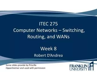
A base and a limit register • the second process in the left memory map • the base register: 30004 • the limit register: 12090 • the range in physical memory this process can access is from 30004 through 42094 (inclusive)
H/W Address Protection with base and limit registers • Protection of memory space is accomplished by having the CPU compare every address generated in user mode with the registers (base and limit registers) • Every illegal memory access results in trap to the OS
Input Queue • A program resides on a disk as a binary executable file • To be executed, the program must be brought into memory and placed within processes • Depending on the memory management in use, the process may be moved between disk and memory during its execution • The processes on the disk are waiting to be brought into memory for execution from the input queue • Input queue–collection of processes on the disk that are waiting to be brought into memory for execution
User programs go through several steps before being run Addresses may be represented in different ways during these steps Instructions Data Addresses in the source program are generally symbolic (int A;) A compiler will typically bind these symbolic address to relocatable addresses (14 bytes from the start of this function) Linkage editor or loader will bind the relocatable addresses to absolute addresses (74014) Multi-step Processing of a User Program
Address Binding of Instructions and Data to Memory Address binding of instructions and data to memory addresses can happen at three different stages • Compile time: If memory location known a priori, absolute code can be generated; must recompile code if starting location changes • Load time: Must generate relocatablecode if memory location is not known at compile time • Execution time: Binding delayed until run time if the process can be moved during its execution from one memory segment to another • Need hardware support for address maps (e.g., base and limit registers)
Logical vs. Physical Address Space • The concept of a logical address space that is bound to a separate physicaladdress space is central to proper memory management • Logical address: generated by the CPU; also referred to as virtual address • Physical address: address seen by the memory unit • Logical and physical addresses are the same in compile-time and load-time address-binding schemes; • Logical (virtual) and physical addresses differ in execution-time address-binding scheme
Memory-Management Unit (MMU) • Hardware device that maps virtual to physical address • In MMU scheme, the value in the relocation register is added to every address generated by a user process at the time it is sent to memory • The user program deals with logical addresses; • it never sees the real physical addresses
The value in the relocation register is added to every address generated by a user process at the time it is sent to memory Base register= relocation register Dynamic relocation using a relocation register
Protection with limit and relocation register • Each logical address must be less than the limit register • The MMU maps the logical address dynamically by adding the value in the relocation register, which is sent to memory
Dynamic Loading • When a program is executed • Routine is not loaded until it is called • Better memory-space utilization; unused routine is never loaded • Useful when large amounts of code are needed to handle infrequently occurring cases • No special support from the operating system is required • The user may design their program to take advantage of this scheme • OS may help the programmer by providing routines to implement dynamic loading
Dynamic Linking • Linking postponed until execution time • Supported by dynamically linked libraries • Small piece of code, stub, used to locate the appropriate memory-resident library routine • Stubreplaces itself with the address of the routine, and executes the routine • Operating system needed to check if routine is in processes’ memory address • Dynamic linking is particularly useful for libraries • System libraries shared by multiple processes
Swapping • A process can be swapped temporarily out of memory to a backing store, and then brought back into memory for continued execution • Swap in, swap out • Backing store–fast disk large enough to accommodate copies of all memory images for all users; must provide direct access to these memory images • Roll out, roll in–swapping variant used for priority-based scheduling algorithms; lower-priority process is swapped out so higher-priority process can be loaded and executed • Major part of swap time is transfer time; • total transfer time is directly proportional to the amount of memory swapped • Modified versions of swapping are found on many systems (i.e., UNIX, Linux, and Windows)
Dispatcher swaps out a processto input queue in the backing storewhen the memory space is not enough Dispatcher swaps in a process from the backing store to ready queue Schematic View of Swapping
Contiguous Allocation • Main memory is usually divided into two partitions: • Resident operating system, usually held in low memory with interrupt vector • User processes then held in high memory • Contiguous Allocation • Each process is contained in a single contiguous section of memory • Relocation-register scheme used to protect user processes from each other, and from changing operating-system code and data • Relocation register contains value of smallest physical address; • limit register contains range of logical addresses –each logical address must be less than the limit register
Several user processes in memory at the same time Each process in a contiguous section of memory Example of Contiguous Allocation
Contiguous Allocation (Cont.) • Hole–block of available memory; holes of various size are scattered throughout memory • Operating system maintains information about:a) allocated partitions b) free partitions (hole) • When a process arrives, it is allocated memory from a hole large enough to accommodate it OS OS OS OS process 5 process 5 process 5 process 5 process 9 process 9 process 8 process 10 process 2 process 2 process 2 process 2
Dynamic Storage-Allocation Problem • First-fit: Allocate the first hole that is big enough • Best-fit: Allocate the smallest hole that is big enough; • must search entire list, unless ordered by size • produces the smallest leftover hole • Worst-fit: Allocate the largest hole; • must also search entire list • produces the largest leftover hole How to satisfy a request of size n from a list of free holes • First-fit and best-fit better than worst-fit in terms of speed and storage utilization
Fragmentation • External Fragmentation–total memory space exists to satisfy a request, but it is not contiguous • Internal Fragmentation–allocated memory may be slightly larger than requested memory; • this size difference is memory internal to a partition, but not being used • Reduce external fragmentation by compaction • Shuffle memory contents to place all free memory together in one large block • Compaction is possible only if relocation is dynamic, and is done at execution time • I/O problem • Latch job in memory while it is involved in I/O
Paging – a memory management scheme • Allows that • Physical address space of a process can be noncontiguous • Process is allocated physical memory whenever the latter is available • Divide physical memory into fixed-sized blocks called frames (size is power of 2, between 512 (=29) bytes and 16384(=214) bytes) • Divide logical memory into blocks of same size called pages • Keep track of all free frames • To run a program of size n pages, need to find n free frames and load program • Set up a page tableto translate logical to physical addresses • No external fragmentationbutinternal fragmentation
Address Translation Scheme • Logical address generated by CPU is divided into: • Page number(p)– used as an index into a pagetable which contains base address of each page in physical memory • Page offset(d)–combined with base address to define the physical memory address that is sent to the memory unit • If the size of the logical address space is 2m, and a page size is 2n addressing units, • The high-order m - n bits of a logical address designates the page number • The n low-order bits designate the page offset page offset page number m - n n
Address Translation Architecture • A pagetablecontains base address of each page in physical memory • A page table is created for each process
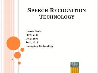
Page (Frame) size: 4 bytes Physical memory: 32 bytes 8 frames 5 bits for addressing 3 bits for page table entry Logical address space: 16 bytes 4 pages 4 bits for addressing Logical address 4 bits Higher 2 bits for page number Lower 2 bits for page offset Logical address 0 (0000) is page 0, offset 0 → 5 x 4 + 0 = 20 Logical address 11 (1011) is Page 2, offset 3 → 1 x 4 + 3 = 7 Paging Example
Page Table Size • Page table size depends on • The size of a logical address space of a process and a page-table entry • Usually, each page-table entry is 4 bytes long, • but that size can vary as well • A 32-bit entry can point to one of 232 physical page frames • If a frame size is 4 (=212)KB • A system with 4-byte page table entries can address 244 bytes (16 TB) of physical memory
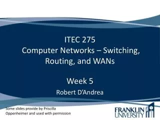
When a new process created with 4 pages of address space OS should check that 4 frames are available A new page table created page 0 → frame 14 page 1 → frame 13 page 2 → frame 18 page 3 → frame 20 Free Frames After allocation Before allocation
Implementation of Page Table • Page table is kept in main memory • Page-tablebase register (PTBR) points to the page table • Page-table length register (PRLR) indicates size of the page table • In this scheme every data/instruction access requires two memory accesses • One for the page table and • One for the data/instruction • The two memory access problem can be solved by the use of a special fast-lookup hardware cache called translation look-aside buffers (TLBs)
Translation look-aside buffer (TLB) • Is an associative, high-speed memory • A cache for the page table • TLB contains only a few of the page-table entries • When a logical address is generated by the CPU, its page number is presented to the TLB • If the page number is found, its frame number is immediately available and is used to access memory • If the page number is not in the TLB (TLB miss), a memory reference to the page table must be made • If frame number is obtained, we can use it to access memory • We add the page number and frame number to the TLB • If the TLB is already full of entries, OS selects one for replacement • Replacement policy: least recently used (LRU), random
Effective Access Time • Hit ratio () • Percentage of times that a page number is found in the TLB • 80% hit ratio: we can find the desired page number in the TLB 80% of the time • Assume that • TLB Lookup time = time unit • Memory access time = τ time unit • Effective Access Time (EAT) EAT = (τ + ) + (2τ + )(1 –) • Assume that • = 80%, = 20 nanosecond, τ = 100 nanosecond • EAT = (100 + 20) x 0.8 + ( 2x100 + 20) x 0.2 = 140 nanosecond
Memory Protection • Memory protection implemented by associating protection bit with each frame • One bit can define a page to be read-only, or read-write • An attempt to write to a read-only page causes a hardware trap to the operating system • Valid-invalid bit is attached to each entry in the page table: • “valid” indicates that the associated page is in the process’ logical address space, and is thus a legal page • “invalid” indicates that the page is not in the process’ logical address space
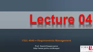
Suppose that in a system with 14-bit address space, 2KB of page (frame) size A process has 6 x 2KB of address space Page table size: 8 (=23) Addresses in pages 1,2,3,4, and 5 are mapped normally through the page table Any attempt to address in pages 6 or 7, will find that the valid-invalid bit is set to invalid, and the trap is generated Valid(v) or Invalid(i) Bit in a Page Table
Page Table Structure • Hierarchical Paging • Hashed Page Tables • Inverted Page Tables
Hierarchical Page Tables • Consider a system with • a 32-bit logical address space, 4KB of page size • Required page table size • (232 / 212 ) x 4 byte = 4 Mbytes→ too big for a page table • Solution to this problem: • Break up the logical address space into multiple page tables • A simple technique is a two-level page table
Two-Level Paging Example • A logical address (on 32-bit machine with 4KB page size) is divided into: • a page number consisting of 20 bits • a page offset consisting of 12 bits • Since the page table is paged, the page number is further divided into: • a 10-bit page number • a 10-bit page offset • Thus, a logical address is as follows:wherep1is an index into the outer page table, and p2 is the displacement within the page of the outer page table page number page offset p2 p1 d 10 12 10
Logical address 32-bit address with 4KB page # of page entries 232 / 214 = 220 20 bits for page number 10 bits for index for outer page table 10 bits for offset # of entries in outer page table 210 # of entries in each sub-page table 210 Two-Level Page-Table Scheme
Address-Translation Scheme • Address-translation scheme for a two-level 32-bit paging architecture
Hashed Page Tables • Common approach for handling address spaces larger than 32 bits • The virtual page number is hashed into a page table. This page table contains a chain of elements hashing to the same location • Each element consists of three fields: the virtual page number, the value of the mapped page frame, a pointer to the next element • Virtual page numbers are compared in this chain searching for a match • If a match is found, the corresponding physical frame is extracted
Inverted Page Table • Each process has an associated page table • Drawback → consumes large amounts of physical memory • Solution → Inverted Page Table • has one entry for each real page of memory • Entry consists of • virtual address of the page stored in that real memory location, • information about the process that owns that page • decreases memory needed to store each page table, but • increases time needed to search the table when a page reference occurs
Inverted page table entry process id, page number The index is the corresponding frame number When a memory reference occurs, <pid, page number> is presented The inverted page table is searched for a match If a match is found at entry i, then < i, offset> is physical address If no match is found, then an illegal memory access Inverted Page Table Architecture
Shared Pages • An advantage of paging is the code sharing • Important in time-sharing environment • Shared code • One copy of read-only code (reentrant code) shared among processes (i.e., text editors, compilers, window systems) • Reentrant code is non-self-modifying code, it never changes during execution • Shared code must appear in same location in the logical address space of all processes • Private code and data • Each process keeps a separate copy of the code and data • The pages for the private code and data can appear anywhere in the logical address space
40 users, each of which executes a text editor Text editor: 150 KB of code, 50 KB of data Total memory space: 200 KB x 40 = 8000 KB If the code is reentrant code, it can be shared among 40 text editors. 150 KB for code is required Total memory space 150 + 50 x 40 = 2150 KB Shared Pages Example
Segmentation • User view of memory for a program • A program is a collection of segments • A segment is a logical unit such as: main program, procedure, function, method, object, local variables, global variables, common block, stack, symbol table, arrays • Segmentation is a memory-management scheme that supports user view of memory
A program is a collection of segments main program subroutine sqrt stack symbol table Elements within a segment are identified by their offset from the beginning of the segment The 1st statement of the sqrt The 5th element in the stack <segment-name, offset> for addressing User’s View of a Program
1 4 2 3 Logical View of Segmentation • A logical address space is a collection of segments • Each segment has its name and a length • <segment-name, offset> is used for addressing • Segmentation maps each segment in the physical memory 1 2 3 4 user space physical memory space
Example • Normally, the user program is compiled, and the compiler automatically construct segments reflecting the input program • A C compiler might create separate segments for the following: • The code • Global variables • The heap, form which memory is allocated • The stacks used by each thread • The standard C library • Libraries might be assigned separate segments • The loader take these segments and assign them segment number
Segmentation Architecture • Each segment is assigned a number: segment-number • Logical address consists of a two tuple: <segment-number, offset> • Segment table– maps two-dimensional physical addresses; each table entry has: • base– contains the starting physical address where the segments reside in memory • limit– specifies the length of the segment • Segment-table base register (STBR) points to the segment table’s location in memory • Segment-table length register (STLR) indicates number of segments used by a program; segment number s is legal if s < STLR