Download
1 / 82
870 likes | 1k Views
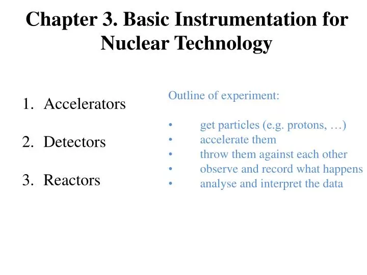
Chapter 3. Basic Instrumentation for Nuclear Technology. Accelerators Detectors Reactors. Outline of experiment:

E N D
Chapter 3. Basic Instrumentation for Nuclear Technology • Accelerators • Detectors • Reactors • Outline of experiment: • get particles (e.g. protons, …) • accelerate them • throw them against each other • observe and record what happens • analyse and interpret the data
1.Accelerators • History-Why • Particle Sources • Acceleration stage • Space charge • Diagnostics • Application
Nature’s Particle Accelerators Naturally occurring radioactive sources: Up to 5 MeV Alpha’s (helium nuclei) Up to 3 MeV Beta particles (electrons) Natural sources are difficult and limited: Chemical processing: purity, messy, and expensive Low intensity Poor geometry Uncontrolled energies, usually very broad Examples from the nature – electrostatic discharge, α- and β-decays, cosmic rays.
“Start the ball rolling…” 1927: Lord Rutherford requested a “copious supply” of projectiles more energetic than natural alpha and beta particles. At the opening of the resulting High Tension Laboratory, Rutherford went on to reiterate the goal: What we require is an apparatus to give us a potential of the order of 10 million volts which can be safely accommodated in a reasonably sized room and operated by a few kilowatts of power. We require too an exhausted tube capable of withstanding this voltage… I see no reason why such a requirement cannot be made practical.
Why study... • The construction, design and operation of particle accelerators uses knowledge from different branches of physics: electromagnetism, high frequency electronics, solid states physics, optics, vacuum technology, cryogenics, ... • Learning about particle accelerator is a good opportunity to learn about many different physical phenomenon.
Why • They have wide ranging applications well beyond physics: health, life science, materials and even archaeology!
Early accelerators 1870: Discovery of the cathode rays by William Crookes- Charged rays - Propagation from the Cathode to the anode A Crookes tube in which the Cathode rays are deflected by a magnetic field. Images source: Wikipedia 1896: J.J. Thomson shows that the cathode rays are made of “particles” and measure the charge/mass ratio.These particles are called “electrons”
Bremsstrahlung • A charged particle emits radiation when it is accelerated. • An electron that Coulomb scatters on a heavy nucleus will change direction => acceleration • Bremsstrahlung, braking radiation, is the name of the radiation emitted when a charged particle scatters on a heavy nucleus. • When a charged beam hits an object, X-rays are emitted. This is used to produce X-rays in hospitals but it is also a source of hazardous radiations in accelerators. • Bremsstrahlung is similar to synchrotron radiation. Image source: http://www.ndt-ed.org/EducationResources/
Improved resolution • In quantum mechanics the wavelength of an object is related to its energy by • The reach better resolutions, the energy of the probe must be increased. • The energy of the electrons in Cathodic ray tubes is limited by the electrostatic generators available. • In the 1930s several generators where invented to produce high electric fields.
vacuum Ion source analyzer acceleration steering
History-Why Particle Sources Acceleration stage Space charge Diagnostics Application • 1.Accelerators
Particle sources • How particles are first produced? • How to extract particles with the right properties? • What are the limitations of the sources? • The quality of the source is very important. If the particles emitted by the source do not have the right properties, it will be very difficult and/or expensive to rectify it later.
Beams of nanoamperes to hundreds of amperes Very thin to very broad beams (μm2 to m2) Negative to highly charged state e to protein molecule
Emission of electron:Thermionic effect (image source: wikipedia) • When a metal is heated more electrons can populate high energy levels. • Above a certain threshold they electrons can break their bound and be emitted: This is thermionic emission.
Work function • To escape from the metal the electrons must reach an energy greater than the edge of the potential well. • The energy that must be gained above the Fermi energy is called the “work function” of the metal. • The work function is a propertyspecific to a given metal. It canbe affected by many parameters(eg: doping, crystaline state,surface roughness,...) • Example values: (image source: wikipedia)
Summary: electrons in solids • At low temperature all electrons are in the lowest possible energy level, below the Fermi level. • As the temperature increase some electrons will go above the Fermi level. • But only those with an energy above the Fermi level greater than the work function are “free”. (image source: http://cnx.org/content/m13458/latest/
Thermionic emission • The Richardson-Dushman equation gives the electronic current density J (A/m-2) emitted by a material as a function of the temperature:With A the Richardson constant: (image source:Masao Kuriki, ILC school)
Thermionic cathode material • Two parameters are important when considering a thermionic cathode material: • W=Work function (as low as possible) • Te=Operation Temperature (preferably high) • Cesium has a low work function (W~2eV) but a low operation temperature (Te=320K) => not good for high current • Metals: Ta (4.1eV, 2680K), W(4.5eV, 2860K) • BaO has good properties (1eV; 1000K) but can oxidize by exposure to air => sinter of BaO+WBaO provided slowly to the surface.
field enhanced thermionic emission • Under a very intense electric field some electrons will be able to tunnel across the potential barrier and become free. • This is known as field effect emission. (image source: answers.com)
Electric field bias • Once the electrons are free they may fall back on the cathode. • To avoid this an electric field needs to be applied. • If a negative potential is applied to the cathode the electrons will be attracted away from the cathode after being emitted. • However this field affects the work function.
Photon-enhanced thermionic emission • A photon incident on a piece of metal can transfer its energy to an electron • If the photon transfers enough energy the electron can be emitted. • By using powerful lasers the photoelectric effect can be used to produce electron beams. • This is known as the photo-electric emission. (image source: wikipedia)
Photo-electric emission (2) • A UV photon at 200nm carries an energy of about 6 eV, this is enough to “jump” over the work function of most metals. • As seen in electromagnetism, electromagnetic waves (photons) can penetrate inside a metal. • The photo-electricemission may thustake place away from the surface. (image source: Dowell et al., Photoinjectors lectures)
The 3 steps of photo-electric emission Photo-electric emission takes place in 3 steps: 1) Absorption of a photon by an electron inside the metal. The energy transferred is proportional to the photon energy. 2) Transport of the photo to the physical surface of the metal. The electron may loose energy by scattering during this process. 3) Electron emission (ifthe remaining energy isabove the work function;including Schottky effect)
Quantum efficiency (QE) • For photo-electric emission, it is useful to define the “quantum efficiency”: • Typical QE for a photo-cathode is only a few percent or less! • The quantum efficiency will decrease during the life of the cathode: it may get damaged or contaminated.
Thermionic emittance (1) • Velocity distribution of thermionic electrons: • The higher the temperature, the wider the transverse energy (momentum) spread. • 300K => 0.049eV spread • 2500K => 0.41eV spread • The transverse momentum spread determines the beam divergence. (image source: Dowell et al., Photoinjectors lectures)
Ion (and proton) sources • An electric discharge creates a plasma in which positively and negatively charged ions are present (as well as neutrals). • If such plasma experiences an intense electric field ions will separate in opposite directions. • This is a rather crude and inefficient (but very simple) way of producing any sort of ions. • In a Penning ion source a magnetic field is used to increase the probability the free electron ionize extra neutrals. (images source: CERN)
Ion source SINCS Source of Negative Ions by Cesium Sputtering - SNICS II Principle of Operation
Focused Ion Beam liquid metal ion source (LMIS),
Electrospray ionisation Tube lens Octapole Lenses ESI needle 4kV Skimmer Acceleration tube 10-3 mbar 10-5 mbar 10-6 mbar 1 mbar Rotary pump Turbo pump Turbo pump Heated Capillary (~180°C) Fused silica capillary Charge Residue Model electrospray droplets undergo evaporation and fission cycles, eventually leading progeny droplets that contain on average one analyte ion or less. The gas-phase ions form after the remaining solvent molecules evaporate, leaving the analyte with the charges that the droplet carried.
History-Why Particle Sources Acceleration stage Space charge Diagnostics Application • 1.Accelerators
Acceleration stage • Only works on charged particles • Electric Fields for Acceleration • Magnetic Fields for Steering • Magnetic fields act perpendicular to the direction of motion. • For a relativistic particle, the force from a 1 Tessla magnetic field corresponds to an Electric field of 300 MV/m Lorentz Force
types of accelerators: electrostatic (DC) accelerators Cockcroft-Walton accelerator (protons up to 2 MeV) Van de Graaff accelerator (protons up to 10 MeV) Tandem Van de Graaff accelerator (protons up to 20 MeV) resonance accelerators cyclotron (protons up to 25 MeV) linear accelerators: electron linac: 100 MeV to 50 GeV proton linac: up to 70 MeV synchronous accelerators synchrocyclotron (protons up to 750 MeV) proton synchrotron (protons up to 900 GeV) electron synchrotron (electrons from 50 MeV to 90 GeV) Induction: Induction linac, betatron
electrostatic accelerators: generate high voltage between two electrodes ⇒ charged particles move in electric field, energy gain = charge times voltage drop; Cockcroft-Walton and Van de Graaff accelerators differ in method to achieve high voltage.
Cockcroft-Walton • High voltage source using rectifier units • Voltage multiplier ladder (made of diodes and capacitors) allows reaching up to ~1MeV (sparking). • First nuclear transmutation reaction achieved in 1932: p + 7Li → 2·4He • CW was widely used as injector until the invention of RFQ Fermilab 750 kV C-W preaccelerator
Van de Graaff Voltage buildup by mechanical transport of charge using a conveyor belt. up to ~20 MV The charged particles are extracted from an ion source housed inside the high-voltage terminal and accelerated down an evacuated tube to ground potential.
Tandem Van de Graaff • Negative ions accelerated towards a positive HV terminal, then stripped of electrons and accelerated again away from it, doubling the energy. • Negative ion source required!
The Million Volt BarrierSummary of Problems in getting HV ~ 1929 Voltage Generators Insulators – 750 kV max holding ! Power Safety in using HV Funding Imagination
RF Accelerators Radiofrequency oscillating voltage • High voltage gaps are very difficult to maintain • Solution: Make the particles pass through the voltage gap many times! • First proposed by G. Ising in 1925 • First realization by R. Wiederöe in 1928 to produce 50 kV potassium ions • Many different types
RF LINAC – basic idea • Particles accelerated between the cavities • Cavity length increases to match the increasing speed of the particles • EM radiation power P = ωrfCVrf2 – • the drift tube placed in a cavity so that the EM energy is stored. • Resonant frequency of the cavity tuned to that of the accelerating field
RF LINAC – phase focusing • E. M. McMillan – V. Veksler 1945 • The field is synchronized so that the slower particles get more acceleration
1.Accelerators • History-Why • Particle Sources • Acceleration stage • Space charge • Diagnostics • Application
1.Accelerators • History-Why • Particle Sources • Acceleration stage • Space charge • Diagnostics • Application
What do you want to know about the beam? • Intensity (charge) (I,Q) • Position (x,y,z) • Size/shape (transverse and longitudinal) • Emittance (transverse and longitudinal) • Energy • Particle losses