Download
1 / 26
260 likes | 469 Views
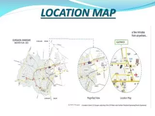
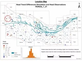
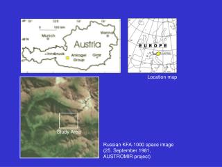
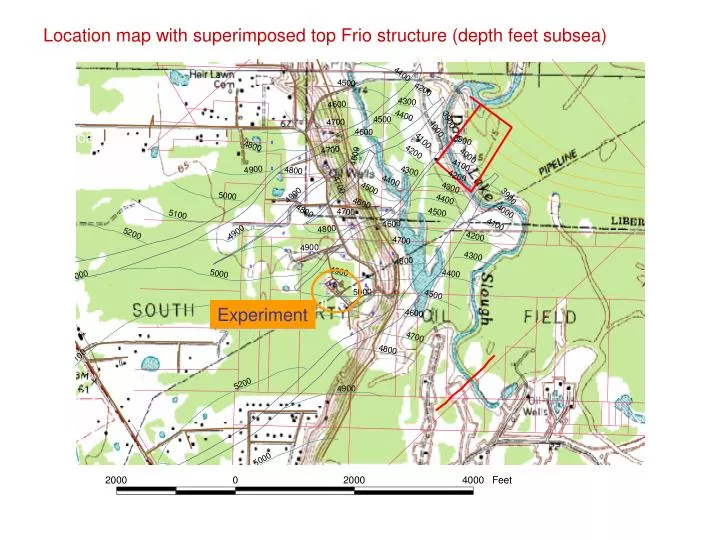
Location map with superimposed top Frio structure (depth feet subsea). Experiment.

E N D
Location map with superimposed top Frio structure (depth feet subsea) Experiment
Setting: The Gulf Coast is host to many heavy industries deeply involved with carbon fuels. This photo shows one of the tubular (pipe) suppliers that supports the oil and gas industries, several refineries, and a gas-fired power plant on US 90 as you drive to the site. Photo: SDH BEG
The Trinity River flood plain is wetland. The site is on the terrace marginal to the wetland and is prone to flooding during heavy rain and high water. Photo: SDH BEG
Texas American tank battery. Oil production has dominated land use for 50 years. Photo: SDH BEG
Access to site is typical oil-field road Photo: P. R. Knox
Sun-Gulf-Humble #4, condition before project start. This well has now been recompleted as an observation well in the Frio. Photo: P. R. Knox
Well pad of Sun-Gulf-Humble #4, looking south condition before project start Photo: P. R. Knox
The well pad was extended, bermed and additional gravel and cement added to stabilize wet clay soils. Onsite pit for cuttings disposal behind, cellar for new well in foreground . Research team visit to pad 4/19/02 Photo: SDH BEG
SGH #4 workover to convert it from oil production to a research observation well. The well was plugged at 5650 feet and the casing perforated to squeeze cement behind casing in the injection zone Photo: Spud Miller, Sandia Technologies
Surface conductor was hammered to refusal at 113 feet. This large diameter pipe prevents wash-out of near surface sediment when the well was being drilled. Photo: Spud Miller, Sandia Technologies
Rigging up Nicklos #1 to drill the injection test well Photo M. H. Holtz, BEG
Sandia Technologies assistant site manager David Freeman working with drilling foreman to control drilling and select data collection points Photo: S. D. Hovorka
Drilling is a 24 hour operation Photo: S.D. Hovorka, BEG
Activities on the derrick floor – setting surface casing Photo: S.D. Hovorka, BEG
Spud Miller, Sandia Technologies site manger shows visitors from Japan the drill bit used to drill the surface hole. Photo: S.D. Hovorka, BEG
To collect core the drill pipe is pulled back to the surface and the drilling bit replaced by a coring bit, which has a hole in the center. Photo: S.D. Hovorka, BEG
Core recovered from selected intervals will be used to understand how CO2 moves underground. This core is from the Anahuac shale that limits upward movement of CO2. Brown ooze is drilling mud with red tracer (Rhodamine WT) in it. Photo: Spud Miller, Sandia Technologies
Technicians from Core Lab quick freeze the core using dry ice (a use of CO2). This is needed because the Frio sandstone are poorly indurated and would break and shift during shipping if not frozen. Photo: S.D. Hovorka, BEG
Core has been slabbed while still frozen, and samples cut for various types of analysis. Photo: S.D. Hovorka, BEG
Schlumberger lifts logging tools to the drill platform in preparation for lowering them down the borehole on wireline. Photo: S.D. Hovorka, BEG
Collecting MDT data. Tool is hung on wire to a depth of 5050 feet while data are collected in the truck. Photo: S.D. Hovorka, BEG
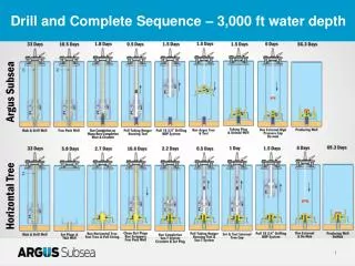
Injection well Observation well Resulting logs Top A ss Top B ss Top C ss Proposed injection zone Prepared by Mark Holtz
C Sand Core Log Depth Log GR & FMI Image CORE GR 5050 5060 5070 5080 Prepared by Shinichi Sakurai
Samples of fluid collected at depth are kept at pressure and shipped to Yousif Kharaka at USGS for chemical analysis of natural gas and water composition. Brines were found to be reasonable representative of subsurface conditions and near saturation with methane. Photo: S.D. Hovorka, BEG
When the borehole was drilled to total depth of 5753 feet and well casing installed, cement was circulated behind the casing to fill annular space. The well is not yet completed. We still have to perforate the casing and so that brine from the rocks can enter the wells. Here rig hands install the cement shoe. Photo: S.D. Hovorka, BEG
Staff from Lawrence Berkeley National Lab set up to collect downhole geophysics including VSP and crosswell data. Photo: S.D. Hovorka, BEG