Download
1 / 61
730 likes | 1.17k Views
Power PMAC Programmed Move Modes November 2013. Five Programmed Move Modes. rapid move mode Trapezoidal/triangular velocity-vs-time profiles Optionally straight-line path in Cartesian system linear move mode Trapezoidal/triangular velocity-vs-time profiles

E N D
Five Programmed Move Modes • rapid move mode • Trapezoidal/triangular velocity-vs-time profiles • Optionally straight-line path in Cartesian system • linear move mode • Trapezoidal/triangular velocity-vs-time profiles • Straight-line path in Cartesian space • circle move mode • Sinusoidal velocity-vs-time profiles • Circular, spiral, elliptical, helical path in Cartesian space • spline move mode • Parabolic velocity-vs-time profiles • Cubic B-spline path • pvt move mode • Parabolic velocity-vs-time profiles • Hermite-spline path
General Move Command Syntax • {axis}{data} [{axis}{data}…] is fundamental move command • {data}can be constant without parentheses, expression inside parentheses • Examples: • X32.7 • A(P10*sind(P11)) • Y-27.264 Z173.19 CC(EndAngle) • Value of {data} is move-end position if axis is in abs mode, distance from start to end position if axis is in inc mode • Axes commanded on same program line move together • But repeated axis command on same program line starts new move • Moves commanded on separate motion program lines execute sequentially • Blended or not depending on mode • Move command on subsequent PLC program line can break into executing (rapid) move
Rapid Mode Moves • Main purpose is minimum-time point-to-point moves, given velocity, acceleration, and jerk constraints • G00 mode in CADCAM/CNC (RS-274) code • Only move mode that can be commanded from PLC programs • No need to declare rapid mode in PLC program • Any move command automatically changes CS’s move mode to rapid • No blending of rapid move with any other move • Can break into rapid move at any time • Programmed triggered moves (e.g. X1000^-30) • Occurrence of trigger causes Power PMAC to break into pre-trigger move • Post-trigger move of specified (signed) distance from position at trigger • Cannot use with axes defined by kinematic subroutines • Newly issued move command (“altered destination”) • From PLC program to C.S. specified by program’s Ldata.Coord value • From on-line “cx” command (e.g. cx X19.93 Y31.25) to addressed C.S. • Note that motion program execution suspended until rapid move ends • Can execute new rapid move command every servo cycle
Rapid Mode Move Control • Same underlying algorithms as jogging and homing-search moves • Velocity control elements • Motor[x].RapidSpeedSel specifies which variable controls speed = 0 (default): Motor[x].MaxSpeed controls magnitude = 1: Motor[x].JogSpeed controls magnitude • Acceleration control elements (used for jogging and homing too) • Motor[x].JogTa >= 0 sets accel time in msec • Motor[x].JogTa < 0 sets (inverse) accel rate in msec2/motor unit • Jerk control elements (used for jogging and homing too) • Motor[x].JogTs >= 0 sets S-curve time in msec • Motor[x].JogTs < 0 sets (inverse) jerk rate in msec3/motor unit • When specifying acceleration and jerk by time: • If JogTa > JogTs, total accel time = JogTa + JogTs (w/ some const accel) • If JogTa < JogTs, total accel time = 2 * JogTs (w/ no const accel) • All parameters are floating-point values; no arbitrary limits • Note: If JogTs < 0, then JogTa must be < 0
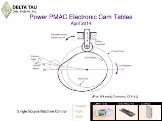
Rapid Mode Move Profile rapid inc X200 Distance = 200,000 m.u. MaxSpeed = 50 m.u./msec JogTa = -10 msec2/m.u.(= 0.1 m.u./msec2) JogTs = -2000 msec3/m.u.(= 0.0005 m.u./msec3)(for 200 msec to Amax)
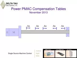
Rapid Mode Triggered Move Profile rapid inc X200^-50 Pre-TriggerDistance <= 200,000 m.u. Post-Trigger Distance = -50,000 m.u. MaxSpeed = 50 m.u./msec JogTa = -10 msec2/m.u.(= 0.1 m.u./msec2) JogTs = -2000 msec3/m.u.(= 0.0005 m.u./msec3)(for 200 msec to Amax)
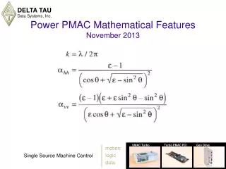
Rapid Move Path Control • Path A: Coord[x].RapidVelCtrl = 0 (all motors move at rapid speed) • Path B: Coord[x].RapidVelCtrl = 1 (only “longest” motor moves at rapid speed), accels specified by (same) rate • Path C: Coord[x].RapidVelCtrl = 1, accels specified by (same) time • Note there is no “vector speed” control in rapid mode Y rapid inc X30 Y10 2 A B C X 1
Linear Mode Moves • For single-axis point-to-point moves, very similar to rapid mode (but different variables control) • Linear moves can blend with linear, circle, pvt moves on the fly • Blending occurs where accel to/from stop would occur without blending • Blending enabled by default, disabled with Coord[x].NoBlend = 1 • No capability to break into executing linear move • Guaranteed straight-line path in 2D/3D Cartesian space • G01 mode in CADCAM/CNC code (RS-274) • Moves can be segmented (Coord[x].SegMoveTime > 0) or not (= 0) • Must be segmented for inverse-kinematic transformation • Must be segmented to use with circle moves • Must be segmented to use buffered lookahead • Commanded simply as {axis}{data}[{axis}{data}…], e.g.: • X5 • X10 Y20 C(Q50+10)
Linear/Circle Mode Move-Time/Speed Control • tm{data}puts in time mode, specifies move time (before acc/dec) in msec • Coord[x].Tm set to value of {data} • F{data} puts in feedrate (velocity) mode, specifies vector speed in axis units per time unit • Axis units set by axis definitions (statements or kinematic subroutines) • Time units set by Coord[x].FeedTime (in msec) – usually sec or min • Coord[x].Tm set to negative of value of {data} • Move time calculated as vector distance / vector speed • Move time also calculated for each non-vector axis as (axis distance / Coord[x].AltFeedrate) • Longest time (vector or non-vector) used for all axes • Only vector feedrate axes involved in these calculations • X, Y, and Z axes are default vector feedrate axes • Axes used can be changed by frax command • Intent is same tool-tip speed in Cartesian space, regardless of direction
Linear Mode Move-Time/Speed Profiles • Distance (ΔP) specified directly in inc mode, indirectly in abs mode • Vector distance of “feedrate axes” (frax) used for rate-specified moves • In time mode, axis velocities computed as axis distance divided by specified move time • In feedrate (velocity) mode, move time is computed as vector distance divided by vector feedrate • Above calculations are done assuming zero accel/decel time • Initial accel time adds Tacc/2 to beginning of move profile • Final decel time adds Tdec/2 to end of move profile • If accel/decel time > move time, does not reach top speed
Linear/Circle Mode Accel/Decel Control • Possibility of separate acceleration and deceleration times • ta{data} sets both accel and decel times (Coord[x].Ta & .Td) • td{data} sets (final) decel time only (Coord[x].Td) • Use td{data} after ta{data} if want different times • Blending between moves uses Ta, not Td • ts{data} sets S-curve time for both accel & decel (Coord[x].Ts) • All times are floating-point values, units of msec, common to all motors • OK to set all accel/decel times to 0.0 (but no limit checking) • Can permit more precise following in external time base • Time base frequency should provide accel & decel profiles • Resulting accel, decel, and jerk can be checked against motor limits • For linear moves with no segmentation (InvAmax, InvDmax, InvJmax) • For segmented linear and circle moves with special lookahead (InvAmax) • All motor times extended when any motor is limited, to maintain coordination and path
Linear Mode Accel/Decel Profiles • Acceleration initially computed as change in speed divided by Ta (or Td for final deceleration) • With no segmentation, this accel rate compared to limit set by Motor[x].InvAmax (or InvDmax), time extended if exceeded. • Initial ramp up to this maximum over Ts time, final ramp down to zero over Ts time (Ts < Ta) • If Ts > Ta, profile never reaches this maximum acceleration • With no segmentation this “jerk” (dA/dt) rate compared to limit set by Motor[x].InvJmax, time extended if exceeded
Vector Feedrate Concept • Many applications want same tool-tip speed in Cartesian space, regardless of direction • Users want controller to calculate individual axis (signed) velocities to achieve this for move in any direction • Underlying motor (actuator) geometry can be Cartesian or non-Cartesian (with kinematic transformations) • To calculate axis velocities for a feedrate-specified move, Power PMAC: • Computes vector distance of move from distances of “vector feedrate axes” by Pythagorean Theorem • Computes move time by dividing commanded vector speed into vector distance • Computes axis velocities by dividing move time into (signed) axis move distance (for both vector feedrate axes and non-vector feedrate axes)
Sample Feedrate Calculations inc; linear; frax(X,Y); // Only X & Y axes in vector calculations X3 Y4 Z12 C90 F10; // Vector distance = sqrt(32 + 42) = 5 // Vector move time = 5 / 10 = 0.5 // VX = 3 / 0.5 = 6 VY = 4 / 0.5 = 8 // VZ = 12 / 0.5 = 24 VC = 90 / 0.5 = 180 inc; linear; frax(X,Y,Z); // X, Y, & Z axes in vector calculations X3 Y4 Z12 C90 F10; // Vector distance = sqrt(32 + 42 + 122) = 13 // Vector move time = 13 / 10 = 1.3 // VX = 3 / 1.3 = 2.31 VY = 4 / 1.3 = 3.08 // VZ = 12 / 1.3 = 9.23 VC = 90 / 1.3 = 69.2 inc; linear; frax(X,Y,Z); F10; // X, Y, & Z axes in vector calculations C90; // Vector distance = sqrt(02 + 02 + 02) = 0 // Vector move time = 0 / 10 = 0 // Non-vector move time = 90 / AltFeedrate // Non-vector time larger, so it is used
Inverse Time Mode • Popular mode in many CNC systems to specify move time as inversely proportional to F-code value • Used often in part programs for 4- and 5-axis machining • Mode often specified by G93 code (disabled by G94) • Time should be specified for each move (not modally) • Specified in Power PMAC with Coord[x].InvTimeMode (not saved) • Uses setting of Coord[x].FeedTime (in msec, usually 60,000) = 0: (default) F value used as vector speed (inverse time mode disabled) > 0: (= 1, 2, or 3) F value used as inverse move time For linear moves: T(msec) = Coord[x].FeedTime/ F value For circle moves: Time calculation dependent on exact setting = 1: For circle moves: T(msec) = Coord[x].FeedTime/ F value = 2: For circle moves: T(msec) = ΔΘX/Y/Z(rad) * Coord[x].FeedTime/ F value = 3: For circle moves: T(msec) = ΔΘXX/YY/ZZ(rad) * Coord[x].FeedTime/ F value
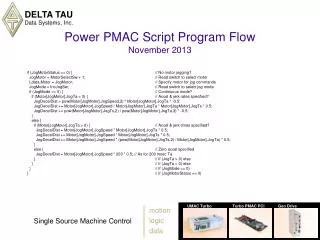
Example Linear-Mode Move Profiles inc linear X100 F40 ta800 ts200 inc linear X100 F40 ta400 td800 ts0
Building Linear Profiles • Start with rectangular profile from distance and speed/time • Create accel/decel slope by “pivoting” vertical about midpoint • This does not change distance covered (area under curve) • Could also be full or partial S-curve acceleration • Blend to next move (if any) starts at point where final deceleration would have begun • Can create blend profile by “pivoting” from vertical about midpoint • Blending does not change distance covered • Blended sequence can continue indefinitely
Building Linear Profiles • Increasing accel/decel time reduces constant-speed time • When accel/decel time equals move time, no more constant-speed time • Full profile is acceleration, blending, deceleration • Good “building-block” approach to arbitrary profiles (but consider PVT and Spline also) • In multi-axis path-based applications, good contouring mode (but consider PVT and Spline also)
Building Linear Profiles • When accel/decel time exceeds move time, solution cannot be obtained • In this case, move time is extended to be equal to accel/decel time • This means that move speed is less than that calculated from programmed feedrate or move time • Accel/decel time serves as minimum move time • OK to set accel/decel time to 0; should control acceleration with lookahead in this case
Multi-Axis Linear Moves, Non-Blended and Blended Y Y X X Vx Vx t t Vy Vy t t
Linear/Circle Mode Move Time Constraints • Same constraints apply whether move time specified directly or calculated from distance and speed • Move-time value has full floating-point resolution and range • If move time < accel time, move time set equal to accel time • If accel time is 0.0, no arbitrary minimum move time • If move time < Sys.ServoPeriod servo update time, move will be calculated, but then skipped over by trajectory servo interpolation • In segmentation mode, if move time < Coord[x].SegMoveTime, move will be calculated, but then skipped over by trajectory segment interpolation • With very short moves, user must be careful not to overwhelm Power PMAC real-time calculation capabilities (run-time error would result and program would halt)
Programmed Move Dynamic Limits • Motor[x].MaxSpeed in motor units/msec • Motor[x].InvAmax in msec2/motor units (Note inversion!) • Motor[x].InvDmax in msec2/motor units (Note inversion!) • Motor[x].InvJmax in msec3/motor units (Note inversion!) • Inversion of accel/decel and jerk limits permits fast multiplication, not slow division, in real-time calculations • All limits operate on linear moves at move calculation time when C.S. not in segmentation mode: Coord[x].SegMoveTime = 0 • Will extend move and accel times from programmed values as necessary to prevent limit violation (Ta and Ts must be > 0.0 to be able to check) • Accel and jerk limiting may not be robust in this mode • Velocity limiting active even in segmentation mode • MaxSpeed & InvAmax operate on segmented moves (linear, circle, pvt) with special lookahead enabled • Limiting is done segment by segment in this mode
Using Linear Mode for Contouring • Many CAD/CAM programs expect linear (G01) mode to generate smooth contours from closely spaced points • Power PMAC’s linear-mode blends have smooth contours • Between blends, have straight-line paths • In these applications, want to minimize/eliminate straight-line portions • Set Coord[x].Ta approximately equal to move times (distance/speed) • Set Coord[x].Ts to 0 for smoothest path • Result is 2nd-order (quadratic) B-spline path (at least approximately) • Commanded path passes to inside of programmed points • Power PMAC has special new linear contouring mode • Commanded linear moves are converted to PVT moves for execution • Enabled with Coord[x].SegLinToPvt > 0, Coord[x].SegMoveTime > 0 • No “flats” between blends • Commanded path passes exactly through programmed points • Resulting trajectory can be processed through buffered lookahead
Using Linear Mode for “Rapid” Moves • For users who want linear-mode attributes for point-to-point moves • Inverse kinematics at segment rate for straight-line path • Lookahead limiting at segment rate (for kinematic axis definitions) • Use same segmentation override as for path moves • Separate acceleration and deceleration constraints • “\” quick-stop command working the same for both move types • Several methods of specifying “rapid” speed • Declare “nofrax” (no vector feedrate axes) for this mode • Coord[x].AltFeedrate sets speed of “longest” axis, shorter axes match this time • Generally not good if have both linear and rotary axes to move in this mode • Restore vector feedrate axes (e.g. “frax(X,Y,Z)”) when leave this mode • Declare high feedrate in this mode (storing present true feedrate) • Rely on Motor[x].MaxSpeed limits in lookahead to control move speed • May need to raise Coord[x].MaxFeedrate as well • Restore last true feedrate (and maybe MaxFeedrate) when leave this mode • Set Coord[x].NoBlend to 1 to disable blending for “rapid” moves
Circle Mode Moves • Two Cartesian axis sets for circular interpolation per C.S. • X/Y/Z: Main Cartesian axis set • XX/YY/ZZ: Secondary Cartesian axis set • Two sets of vector components (for normal and center vectors) • I/J/K: for X/Y/Z axis set • II/JJ/KK: for XX/YY/ZZ axis set • Center vector usually specified from move start point (INC(R) mode ) • ABS(R) mode sets center vector specification from programming origin • “R” radius specification permitted for X/Y/Z set only • Trajectory must be segmented with Coord[x].SegMoveTime > 0 • Existing enhancements carry over from PMAC/Turbo PMAC • Any plane in 3D Cartesian space can be defined • Other axes are linearly interpolated: helical, tangent axes • Automatic spiral generation when end radius != start radius • With virtual “cross” axis, can use for simple sinusoidal profile generation • G02 (circle1) & G03 (circle2) modes in CADCAM/CNC code (RS-274)
+Z +Z Normal Vectors forCircle Move PlaneDefinition CW G17 (default) CW +X +Y +X +Y normal K-1 normal K1 • Figures show “single-component” vectors with the planes and clockwise arc sense they define • Magnitude of vector does not matter • Negative vector defines clockwise sense according to standards • Combinations of vector components can be used to define “tilted” planes – e.g. normal K-0.866 J-0.5 • Same plane used for 2D tool-radius compensation and corner angle calculations +Z +Z CW G18 CW +X +Y +X +Y normal J-1 normal J1 +Z +Z CW G19 CW +X +X +Y +Y normal I-1 normal I1
Circle Mode Limiting Elements • Coord[x].MinArcLen (in radians) • If arc distance from start point to end point is less than this, points are considered same, and full circle is executed • Allows for some roundoff error in destination position for full circles • Coord[x].MaxCirAccel (in axis units per time-unit2) • If centripetal acceleration (V2/R) at programmed speed exceeds this limit, speed is lowered so limit not exceeded • Limiting done at move calculation time, before segmentation and lookahead, yielding more segments, so less segmentation error • Provides more accurate small circles than if limiting acceleration in lookahead • Coord[x].RadiusErrorLimit (in axis units) • Circle move command does not force end point to be same distance from center as start point is • If distances not same, Power PMAC can compute spiral path to end • If this limit > 0, program stopped if change in distance greater than limit • If this limit = 0 (default), no checking performed • Set to small non-zero value if do not intend to command spirals
Path Blending in Linear and Circle Modes • Commanded blended path same in both directions • If unblended moves would provide sharp corner, blended path provides a rounding to the inside • Ends of blended path are at points where deceleration to stop would begin, and acceleration from stop would end • Blends with circle moves are not exactly on arc path, even for tangent blends
Cornering Control Features • Several saved setup elements control behavior at path “corners” • For linear and circle moves in XYZ Cartesian programming space • normal vector defines plane in which corner angles evaluated • Coord[x].CornerBlendBp specifies which corners are blended • If cos(Δθ) >= CornerBlendBp (shallow angle), corner is blended • If cos(Δθ) < CornerBlendBp (sharp angle), corner is not blended • Coord[x].CornerDwellBp specifies which (unblended) corners have automatic dwell inserted (of Coord[x].AddedDwellTime) • Coord[x].InPosTimeout specifies whether (unblended) corners wait to become “in position” before executing next move or dwell • Coord[x].CornerRadius specifies “size” of corner blend; automatically computes accel time based on speed and corner Δθ; S-curve time is 0 • Coord[x].CornerAccel specifies vector accel at (blended) corners; automatically computes accel time based on speed and corner Δθ • Coord[x].CornerError specifies size of deviation of corner blend path from unblended corner
Specified-Time Blending • Specified blending time (Ta) is default mode • Properties of this mode: • Blend radius increases proportionally with speed • Blend accel increases proportionally with speed • Blend radius decreases with sharper angles (~inversely proportional) • Blend accel increases with sharper angles (~proportionally) • Increasing S-curve (Ts) time “squares up” corner blends • Segmented lookahead can alter speed along path, but not the path itself
Specified-Radius Blending • Selected by setting saved element Coord[x].CornerRadius > 0.0 • Value specifies “radius” of blend (actual radius of curvature at beginning and end of blend) • Blend time automatically calculated to achieve this • No S-curve time used in this mode • Properties of this mode: • Blend time inversely proportional to speed • Blend accel increases with square of speed • Blend error constant over speed • Blend time increases with sharper angles (~proportionally) • Blend accel ~constant over range of angles • Blend error increases with sharper angles • This mode generally used to get a fixed corner “size”
Specified-Accel Blending • Selected by setting saved element Coord[x].CornerAccel > 0.0 • Value specifies vector acceleration at blend • Properties of this mode: • Blend time increases proportionally with speed • Blend radius increases with square of speed • Blend error increases with square of speed • Blend time increases with sharper angle (~proportionally) • Blend radius decreases with sharper angle (~inversely proportional) • Blend error increases with sharper corners • This mode generally used to get smallest possible corner within acceleration constraints
Specified-Error Blending • Selected by setting saved element Coord[x].CornerError > 0.0 • Value specifies path error at blend • Properties of this mode: • Blend time increases proportionally with speed • Blend radius constant over speed • Blend accel increases with square of speed • Blend time decreases with sharper angle • Blend radius decreases with sharper angle • Blend accel increases with sharper angle • This mode generally used to get smallest possible corner within acceleration constraints
2D Tool (Cutter) Radius Compensation • Permits automatic offset of tool-center path by radius so tool edge-path along part can be programmed • Coord[x].CCDistance specifies number of in-plane moves to pre-compute and check for possible interference • Coord[x].CCSize specifies number of pre-computed moves that can be buffered: in-plane, out-of-plane, and zero-distance • normal command vector specifies plane for offset • ccr{data} specifies radius, and so offset magnitude, in axis units • ccmode1 turns on compensation to left (in direction of travel) (G41) • ccmode2 turns on compensation to right (in direction of travel) (G42) • ccmode0 turns off compensation (G40) • Coord[x].CCAddedArcBp specifies which corners have added arcs on outside corners to keep tool close to part • If cos(Δθ) >= CCAddedArcBp (shallow angle), moves blended directly • If cos(Δθ) < CornerBlendBp (sharp angle), arc is added to round corner
2D Cutter Comp Inside Corners • “Inside corner” occurs when path direction changes in direction of comp offset • Power PMAC computes intersection of offset paths • Execution can be blended or not at compensated intersection point • Same cornering “rules” apply as for uncompensated corners
2D Cutter Comp Shallow Outside Corner • “Outside corner” occurs when path changes direction in opposite direction from comp offset • Path at corner dependent on change in angle and value of Coord[x].CCAddedArcBp • If cosine of change in directed angle of programmed path > CCAddedArcBp (“shallow corner”), offset paths are extended and directly intersect • Same cornering “rules” apply as for uncompensated corners
2D Cutter Comp Sharp Outside Corner • If cosine of change in directed angle is less than CCAddedArcBp, the two moves do not directly intersect • An arc move is added between incoming and outgoing moves to go around corner • Prevents tool from getting too far from corner point • Added arc treated as move for cornering “rules”; 0-degree change in angle at both ends • Default for CCAddedArcBp is 0.0, for 90° threshold
2D Comp – Interference/Overcut Problem • Compensated path can cause “overcut” if radius is too big for feature being cut • Problem is indicated by reversal and/or intersection on compensated path • This plot shows problem in compensated (top) path going into pocket of uncompensated (bottom) path • Interference check disabled by setting bit 2 (value 4) of Coord[x].CCCtrl to 1 (good for debugging)
2D Comp – Interference/Overcut Solution • Power PMAC can scan ahead to look for reversal and/or intersection in compensated path • If Coord[x].CCCtrl bit 1 = 0, program is aborted when problem is found, before problem move is executed (good to catch programming error) • If Coord[x].CCCtrl bit 1 (value 2) = 1, path between intersecting points is removed (good for initial rough cut)
3D Tool (Cutter) Radius Compensation • Unlike traditional 2D compensation, offset direction can be in any orientation; specified every move • Coord[x].CC3Data structure specifies tool-nose geometry as a set of arcs (up to 15) in a lookup table • ccmode3 turns on 3D compensation (no left or right mode as direction is specified explicitly) • ccmode0 turns off 3D compensation • nxyz I{data} J{data} K{data} program command specifies surface-normal vector (changeable every move) • txyz I{data} J{data} K{data} program command specifies tool-orientation vector (changeable every move), does not command angle • Based on the two vector orientations and the tool-nose table, offset is calculated and added to programmed XYZ point • No corner calculations or interference checks • Intended for contouring applications with short linear moves
3D Comp Tool Tip Geometry User sets: Coord[x].CC3Data[0].ToolRadius = TR0 Coord[x].CC3Data[0].ToolOffset = TO0 (values for higher indices i are calculated automatically) Coord[x].CC3Data[i].CutRadius = Ri Coord[x].CC3Data[i].NdotT = cos Θi for i = 0 until cos Θi = 1.0
Power PMAC Buffered Lookahead • Special algorithm that “scouts ahead” in segmented move trajectory (linear, circle, pvt modes), looking for violations of motor limits • Position limits Motor[x].MinPos and Motor[x].MaxPos • Velocity limit Motor[x].MaxSpeed • Acceleration limit (inverse) Motor[x].InvAmax • When limit violation is detected in a segment, motion is slowed at that point just enough so that limit is no longer exceeded • Algorithm then works backward from this point through pre-calculated trajectory so that motion can be slowed to problem point without violating acceleration limits • Does not change programmed path, just how fast path is traversed • Permits accel and decel over multiple programmed moves • Permits decel into tight corner and accel out of it, so they can be made within accel constraints without slowing everywhere • Permits stopping at position limits, not past them
Lookahead for Multi-Block Accel/Decel V ACCEL & DECEL TIME MUST BE EQUAL TO OR SHORTER THAN BLOCK MOVE TIME Before Lookahead F100 ta5 X1 X2 X3 X4 X5 X6 X7 X8 X9 X10 DWELL50 1 2 3 4 5 6 7 8 9 10 T V After Lookahead ACCEL & DECEL CONTROLLED BY SPECIFIED ACCEL LIMIT 1 2 3 4 5 6 7 8 9 10 T
5 5 6 2 1 2 4 3 4 3 1 7 Lookahead for Tight Corners VX Y F50 X10 Y10 X0 Y20 5 Time 4 3 2 VY 1 Time X Before Lookahead F50 X10 Y10 X0 Y20 7 VX Y 6 Time 5 ACCEL & DECEL CONTROLLED BY SPECIFIED G’s AT CORNER 4 3 VY 2 1 Time X After Lookahead
Implementing Buffered Lookahead • Calculate required lookahead distance/time • Required time to lookahead in programmed trajectory is top speed divided by maximum accel (= stopping time) • Top speed comes from lower of Coord[x].MaxFeedrate, Motor[x].MaxSpeed • Maximum accel comes from Motor[x].InvAmax • Divide this time by Coord[x].SegMoveTime to get number of segments to look ahead • Reserve memory for lookahead buffer • Must be at least large enough for required lookahead length • Larger buffer preserves trajectory history for reverse/retrace operation • &x define lookahead n command reserves memory for n segments • Axes must already be defined in the coordinate system • Minimum size of 2048 segments • Tell coordinate system to do lookahead for segmented moves • Set Coord[x].LHDistance to number of segments of desired lookahead • Operation of lookahead is then automatic and transparent
Reversal/Retrace in Lookahead • “Oversized” lookahead buffer provides trajectory history • Can traverse path backwards to beginning of buffer • Reverse execution and all transitions obey same limits as forward • Can reverse through dwell, but uses no dwell time • Commands (on-line & [buffered]) to manage execution • \ [lh\]: Quick stop – fastest stop (from either direction) within acceleration constraints • < [lh<]: Start reverse execution (from forward or stopped) • > [lh>]: Resume forward execution (from reverse or stopped) • Rules for synchronous assignments during reversal and “recovery”: • Explicit synchronous assignments (e.g. M1==1) do not “undo” during reversal, or execute again during recovery • Synchronizing label assignments to Coord[x].Nsyncdo change appropriately during reversal and recovery • Explicit synchronous assignments start executing again when enter previously unexecuted part of trajectory