Download
1 / 49
490 likes | 600 Views
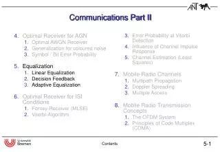
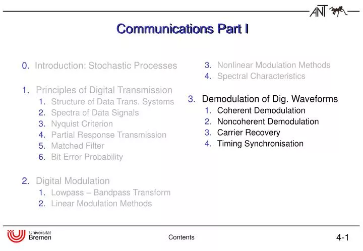
0. Introduction: Stochastic Processes Principles of Digital Transmission Structure of Data Trans. Systems Spectra of Data Signals Nyquist Criterion Partial Response Transmission Matched Filter Bit Error Probability 2. Digital Modulation Lowpass – Bandpass Transform

E N D
0.Introduction: Stochastic Processes Principles of Digital Transmission Structure of Data Trans. Systems Spectra of Data Signals Nyquist Criterion Partial Response Transmission Matched Filter Bit Error Probability 2.Digital Modulation Lowpass – Bandpass Transform Linear Modulation Methods 3.Nonlinear Modulation Methods 4. Spectral Characteristics Demodulation of Dig. Waveforms Coherent Demodulation Noncoherent Demodulation Carrier Recovery Timing Synchronisation Communications Part I Contents
Disadvantage: delay in synchroni-sation loop caused by group delay of lowpass filters Advantage: fast synchronisation loop 3.1 Coherent DemodulationBasic Structures of Coherent Receivers Lowpass Filter - Structure Quadrature filter-Structure Coherent Demodulation
Coherent DQPSK Demodulator Coherent Demodulation
Coherent Demodulation of MSK Signals Reminder: FSK with Interpretation as Offset-QPSK Decoding: Coherent Demodulation
Coherent Demodulation of MSK Signals with Precoding Description of MSK as Offset-QPSK Coherent Demodulation
Coherent Demodulation of MSK Signals with Precoding Avoid decoding of data differential, nonrecursive Precoding Coherent Demodulation
Coherent Demodulation of MSK Signals with Precoding Precoding Multiplication with results in derotation Coherent Demodulation
Linear Model for nonlinear CPM SignalsLaurent Approximation Exact CPM signal: For limited L and define a limited phase impulse and a base impulse as well as timeshifted version Coherent Demodulation
Laurent Approximation (ctd.) From the basic impulse and its timeshifted versions we can derive elementary impulses where . For the definition of we need in a binary representation: The elementary impulses are defined as: Coherent Demodulation
Laurent Approximation (ctd.) Elementary impulses for 2 REC with Coherent Demodulation
Laurent Approximation (ctd.) Construction of elementary impulses Coherent Demodulation
Laurent Approximation (ctd.) Elementary impulses for GMSK and 4REC Coherent Demodulation
Laurent Approximation (ctd.) Defining For : Under previously given conditions a CPM signal can be described as Assuming that elementary impulse has significantly greater energy than all other impulses ( to ) we get the approximation Coherent Demodulation
Laurent Approximation: Complex envelopes of GFSK signals Coherent Demodulation
Laurent Approximation: S/N-Ratio Coherent Demodulation
Eyepatterns for coherent demodulation of GMSK Coherent Demodulation
Coherent Demodulation of CPM Signals Coherent Demodulation
transfering received signal into baseband without carrier synchronisation noncoherent structure: 3.2 Noncoherent Demodulation definition: typical: use of nonlinear systems for demodulation example: FM demodulation problem: linear channel distortion nonlinear distortion after demodulation difficult equalization Noncoherent Demodulation
Noncoherent DPSK Receiver compared with coherent structure: differential demodulation before decision phase error due to carrier frequency offset Noncoherent Demodulation
Noncoherent DPSK Receiver (cont.) (otherwise: decision errors) M-ary PSK: drawbacks of noncoherent DPSK demodulation: • 2. Nyquist criterion is not fulfilled • influence of noise (multiplication of noisy signal) Noncoherent Demodulation
Eyepatterns of noncoherent DQPSK Demodulation Noncoherent Demodulation
Signal Constellation of noncoherent DQPSK Demodulation Noncoherent Demodulation
Differential Demodulation of CPM signals Complex envelope of CPM signal Where is the deviation of the carrier frequency used at the receiver compared to the true FSK carrier frequency Multiplication with the complex conjugate signal delayed by one symbol intervall results in for 1-REC-FSK signal Noncoherent Demodulation
Sampling at symbol rate under concideration of finite length of results in By taking the argument of the above expression data value can be extracted Noncoherent Demodulation
The demodulator is optimal for , i.e. MSK signals. Of disadvantage are values of close to 1 because does not contain phase information ( or ) Noncoherent Demodulation
Example: GMSK demodulation ; nonrecursive approximation is broadened compared to ð increase of ISI Measurements: Equalization, Viterbi detection Noncoherent Demodulation
Discriminator demodulator for CPM signals CPM signals are frequency modulated signals ð demodulation with conventional FM demodulator Ideal: derivation in time of instantaneous phase For FSK signal with after sampling at data decision possible Noncoherent Demodulation
Discriminator demodulator for CPM signals Integration over one symbol intervall is not in terms of matched filtering Limit of when using a digital FM demodulator: is limited by and thus much larger than for differential demodulator Noncoherent Demodulation
3.2 Carrier SynchronisationCarrier Synchronisation on RF Example: 2 ASK • spectrum doesn´t contain carrier frequency • extracting carrier frequency out of RF signal with squaring loop Carrier Synchronisation
Carrier Synchronisation: Phase locked loop (PLL) block diagramm: PLL: Phase Locked Loop phase detector BP LP loopfilter 90° VCO: Voltage Controlled Oscillator VCO Carrier Synchronisation
PLL contains of • phase detector • loop filter • voltage controlled oscillator (VCO) Phase Locked Loop (cont.) • squaring input signal (removing data): • removing DC (bandpass filtering): • synchronisation in phase locked loop (PLL) VCO output: Carrier Synchronisation
Phase Locked Loop (cont.) and phase detector compares phase of multiplication loop filter suppresses noise and higher frequency signal components VCO input: ~ phase error because is small (VCO center frequency ) loop islocked: (remaining phase error) instead of M-PSK: Carrier Synchronisation
(during ) rotation of signal constellation in complex plane due to frequency offset is Decision Feedback Carrier Synchronisation (Baseband) Idea: Receiver knows correct phases out of modulation alphabet comparing input and output of decider decision feedback carrier synchronisation demodulation of received signal with frequency offset Carrier Synchronisation
integrating by filter yields to phase error signal at decider input: estimating (condition: correct decision, ) DF Carrier Synchronisation (cont.) correction term is accumulation of : Carrier Synchronisation
DF Carrier Synchronisation: Block Diagram : received signal (baseband) decider + + - + Carrier Synchronisation
DF Carrier Synchronisation: Example signal constellation without synchronisation: QPSK: correction term: if rotation of signal constellation during T is greater than : wrong decision ( ) carrier synchronisation failes!! Carrier Synchronisation
frequency offset • phase jitter additionally: phase error estimation is disturbed by channel noise noise at decider input: Carrier Synchronisation Loop – Linearized Model up to now: only frequency offset now: phase error results of phase error (ramp) instantanous phase error after correction: Carrier Synchronisation
Carrier Synchronisation Loop noisy phase error estimation: power of phase noise: linearized model for carrier synchronisation loop (considering only phase): + remaining phase error - noise Carrier Synchronisation
example: first order loop filter Remaining Phase Error (only Frequency Offset) using z-transformation: loop transfer function: Carrier Synchronisation
Remaining Phase Error with 1st Order Loop Filter remaining phase errordue to a frequency offset (steady state, 1st order loop filter): Carrier Synchronisation
but: for loop stability ! Remaining Phase Error (cont.) as big as possible small remaining phase error : choose M-ary PSK: (= all decisions correct) Carrier Synchronisation
4 3 2 1 stability: -3 -2 -1 0 Remaining Phase Error with 2nd Order Loop Filter no remaining phase error: choose 2nd order loop filter stability Carrier Synchronisation
phase jitter: : jitter frequency : amplitude jitter transfer function: (1st order loop filter) remaining phase jitter: Remaining Phase Error with Phase Jitter (Phase Noise) assumption: Carrier Synchronisation
Phase Jitter, Phase Noise 2nd order loop filter: noise transfer function: , 1st order: power of remaining phase noise: Carrier Synchronisation
Phase Noise Carrier Synchronisation
system impulse response fits 1st Nyquist condition idea: synchronisation on zeros of : sampling error 3.4 Timing Synchronisation: Decision Feedback Rate Control assumption: received signal is equalized (cross correlation : before and after decision) criterion for symbol clock correction: inphase component: where Synchronisation
no decision errors Decision Feedback Rate Control Synchronisation
else ~ ! Decision Feedback Rate Control uncorrelated zero mean data: with : Synchronisation
- + DCO mean Decision Feedback Rate Control block diagram: sample time tracking time averaging ~ t Synchronisation