Download
1 / 64
650 likes | 788 Views
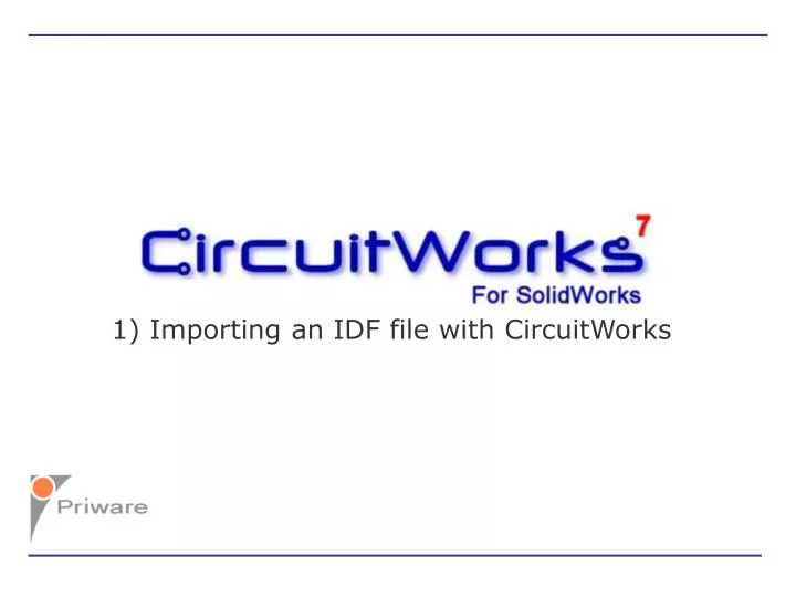
1) Importing an IDF file with CircuitWorks. CircuitWorks adds a Menu and Toolbar into SolidWorks. CircuitWorks Menu. CircuitWorks adds a Menu and Toolbar into SolidWorks. CircuitWorks Menu. CircuitWorks Toolbar. To process an IDF or PADS file, click the ‘Open IDF File’

E N D
CircuitWorks adds a Menu and Toolbar into SolidWorks
CircuitWorks Menu CircuitWorks adds a Menu and Toolbar into SolidWorks
CircuitWorks Menu CircuitWorks Toolbar
To process an IDF or PADS file, click the ‘Open IDF File’ icon or select ‘Open IDF File…’ from the menu
Open IDF File icon To process an IDF or PADS file, click the ‘Open IDF File’ icon or select ‘Open IDF File…’ from the menu
CircuitWorks will start, briefly displaying licence and version information
CircuitWorks’ Import Wizard guides the user through importing an IDF file. The first stage is to select board cut-outs
CircuitWorks shows a preview of the board and its cut-outs CircuitWorks’ Import Wizard guides the user through importing an IDF file. The first stage is to select board cut-outs
Un-checking the boxes removes the cut-outs. Checking the boxes adds the cut-outs as required CircuitWorks’ Import Wizard guides the user through importing an IDF file. The first stage is to select board cut-outs
These controls allow the user to zoom in or out of the preview image CircuitWorks’ Import Wizard guides the user through importing an IDF file. The first stage is to select board cut-outs
When the cut-outs have been selected, clicking ‘Next’ continues to the next stage of the Import Wizard
The next stage shows how many non-plated holes there are in the IDF file
The total number of non-plated holes found is shown here The next stage shows how many non-plated holes there are in the IDF file
Holes in the IDF file are either associated with the board or with the components The total number of non-plated holes found is shown here The next stage shows how many non-plated holes there are in the IDF file
Holes in the IDF file are either associated with the board or with the components Checking this option creates the non-plated holes associated with the board The next stage shows how many non-plated holes there are in the IDF file
Holes in the IDF file are either associated with the board or with the components Checking this option creates the non-plated holes associated with the components on the board
CircuitWorks displays the minimum and maximum diameters found for each hole type
By checking this option and editing the size range. CircuitWorks can be configured to only create board non-plated holes within a certain range of diameters
In the same way, this option configures CircuitWorks to only create component non-plated holes within the specified range of diameters
Checking this option will only include non-plated holes in the SolidWorks assembly that are associated with certain components
The user can select which components holes in include in the assembly from the pull-down list
In this example, only the non-plated holes associated with components PL7 and TR8 will be added to the board part in SolidWorks
When the non-plated hole options have been set, clicking ‘Next’ continues to the next stage
The next stage of the Wizard shows how many plated holes are in the IDF file
Plated holes are the conductive holes in the board which can be associated either with the board or the components The next stage of the Wizard shows how many plated holes are in the IDF file
392 Plated holes found in the IDF file The next stage of the Wizard shows how many plated holes are in the IDF file
392 Plated holes found in the IDF file None of the holes are associated with the board The next stage of the Wizard shows how many plated holes are in the IDF file
None of the holes are associated with the board All 392 holes are associated with the components on the board The next stage of the Wizard shows how many plated holes are in the IDF file
All 392 holes are associated with the components on the board Plated holes can be filtered by size or component in the same way as the non-plated holes in the previous stage
When the plated hole options have been set, clicking ‘Next’ continues to the next stage
The ‘Component Heights’ page of the Import Wizard allows the user to edit the heights of the components in the IDF file if required
Green icons indicate components in the IDF file with a non-zero height The ‘Component Heights’ page of the Import Wizard allows the user to edit the heights of the components in the IDF file if required
Red icons indicate components in the IDF file with zero height The ‘Component Heights’ page of the Import Wizard allows the user to edit the heights of the components in the IDF file if required
Expanding the icon shows the current height and units. Here the component height is 0 Thou
A new height can be defined for the component: 30 Thou in this example.
Display options allow the user to view the components by name or part number
Powerful search controls allow the user to locate a particular component easily
When any heights have be changed as required, clicking ‘Next’ continues to the next stage of the Import Wizard
The ‘Component Filters’ page of the Import Wizard allows the user to set criteria to include or exclude components from the final SolidWorks assembly
Components can be Filtered out of the SolidWorks assembly in a number of ways The ‘Component Filters’ page of the Import Wizard allows the user to set criteria to include or exclude components from the final SolidWorks assembly
Components can be Filtered out of the SolidWorks assembly in a number of ways Components can be filtered by their name The ‘Component Filters’ page of the Import Wizard allows the user to set criteria to include or exclude components from the final SolidWorks assembly
Components can be Filtered out of the SolidWorks assembly in a number of ways Components can be filtered by their name The ‘Component Filters’ page of the Import Wizard allows the user to set criteria to include or exclude components from the final SolidWorks assembly
Components can be Filtered out of the SolidWorks assembly in a number of ways Lists of components to include or exclude in the SolidWorks assembly can be added with full support for wildcard characters The ‘Component Filters’ page of the Import Wizard allows the user to set criteria to include or exclude components from the final SolidWorks assembly
Components can be Filtered out of the SolidWorks assembly in a number of ways Commonly used filter settings can be saved to be used again in future The ‘Component Filters’ page of the Import Wizard allows the user to set criteria to include or exclude components from the final SolidWorks assembly
Components can be Filtered out of the SolidWorks assembly in a number of ways Components can also be filtered from the assembly by their height