Download
1 / 37
370 likes | 521 Views
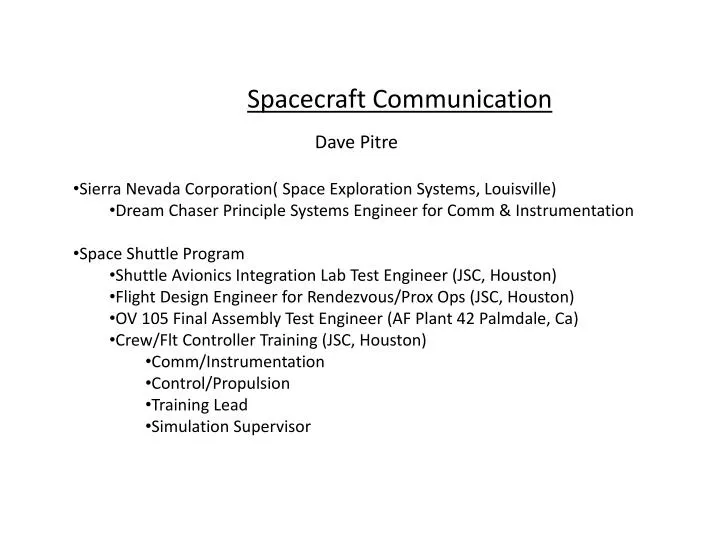
Spacecraft Communication. Dave Pitre Sierra Nevada Corporation( Space Exploration Systems, Louisville) Dream Chaser Principle Systems Engineer for Comm & Instrumentation Space Shuttle Program Shuttle Avionics Integration Lab Test Engineer (JSC, Houston)

E N D
Spacecraft Communication • Dave Pitre • Sierra Nevada Corporation( Space Exploration Systems, Louisville) • Dream Chaser Principle Systems Engineer for Comm & Instrumentation • Space Shuttle Program • Shuttle Avionics Integration Lab Test Engineer (JSC, Houston) • Flight Design Engineer for Rendezvous/Prox Ops (JSC, Houston) • OV 105 Final Assembly Test Engineer (AF Plant 42 Palmdale, Ca) • Crew/Flt Controller Training (JSC, Houston) • Comm/Instrumentation • Control/Propulsion • Training Lead • Simulation Supervisor
What does a spacecraft communication systems engineer do? • Analyze Comm System Requirements • Design Comm System Architecture • Procure Comm System Hardware/Software • Test Comm System Hardware/Software • Integrate Comm System Hardware/Software • Install/Test Comm System Hardware/Software • Maintain Comm System Hardware/Software • Train Comm System Hardware/Software
Systems Level Overview Communication Networks Satellite/Ground Voice RF Systems Data/Telemetry Commands Video MCC
Challenges Unique to Space Communication • Distance • Speed • Line of sight • Ground Track • Earth surface radiation limit • Limited number of users
USA004460Basic Ground Station Line of Sight Horizon line LOS Loss of Signal UPLINK DOWNLINK AOS Acquisition of Signal 126 52
TCS HTS Orbit Ground Precession NHS CTS VTS WLP DFR MILA and PDL GTS DGS
USA004460Rev A ZOE: ZONE OF EXCLUSION (LASTS 5-15 MINUTES) TDRS EAST and WEST COVERAGE TDRSEAST TDRSWEST Atlantic Pacific Indian Ocean TDRS Z 67
Practical Examples Tracking Data Commands Relay Satellite Telemetry WSC Commands Telemetry GSFC GSTDN MCC AFSCN ARTS
Practical Examples Payload Commands Telemetry Voice Data EVA Uplink Downlink GSFC GSTDN MCC AFSCN ARTS
Practical Examples Payload Tracking Data Commands Relay Commands/Data/Voice Telemetry Satellite Telemetry/Data/Voice Voice Data WSC EVA Uplink Uplink Downlink Downlink GSFC GSTDN MCC AFSCN ARTS
Practical Examples Space Station Payload Commands/Data/Voice Telemetry/Data/Voice Tracking Data Commands Relay Commands/Data/Voice Telemetry Satellite Telemetry/Data/Voice Voice Data WSC EVA Uplink Uplink Downlink Downlink GSFC GSTDN MCC AFSCN ARTS
RF OverviewElectromagnetic Waves • Light, electromagnetic waves, radiation = electromagnetic energy. • This energy can be described by frequency, wavelength, or energy. • Radio usually described in terms of frequency (Hertz).
RF OverviewModulation and Waveforms Modulation Data Amplitude Modulation Freq Modulation
RF OverviewSignal Power Power is used to quantify a signal, instead of amplitude, and is expressed in Watts. For low-frequency signals, the power is given by P = IE
RF OverviewSignal Power Transmitter Power Output In radio transmission, transmitter power output (TPO) is the actual amount of power (in watts) of radio frequency (RF) energy that a transmitter produces at its output. Effective Isotropic Radiated Power Power that comes off an antenna is measured as effective isotropic radiated power (EIRP). EIRP is the value that regulatory agencies, such as the FCC, use to determine and measure power limits in applications. TPO EIRP Transmitter cable
RF OverviewDecibels • The decibel is a unitless method of expressing the ratio of two quantities. • The expression is in terms of the logarithm to base 10 of the ratio instead of the raw ratio. • This is done for convenience in expressing the ratio of numbers many magnitudes apart with decibel numbers that are not as large. PdBm=10log10(Pwatts/1mW)
RF OverviewDecibels The advantage of using decibels instead of Watts to express the power of a signal along an RF is that instead of dividing or multiplying powers to take care of amplifications and attenuations, we just add or subtract the gains and the losses expressed in decibels TPO EIRP Transmitter cable
RF OverviewAnalog v. Digital Analog to Digital Conversion (A/D)
RF Overview Signal to Noise Ratio Signal-to-noise ratio (often abbreviated SNR or S/N) is a measure that compares the level of a desired signal to the level of background noise. It is defined as the ratio of signal power to the noise power. A ratio higher than 1:1 indicates more signal than noise.
RF Overview Bit Error Rate • For digital communications, there is a need for end-to-end performance measurements. • The measure of that performance is usually bit-error rate (BER), which quantifies the reliability of the entire radio system from “bits in” to “bits out,” including the electronics, antennas and signal path in between. • On the surface, BER is a simple concept— its definition is simply: • BER = Errors/Total Number of Bits
RF Overview Latency • Latency is a measure of time delay experienced in a system, ccontributors to latency include: • Propagation: This is simply the time it takes for information to travel between one place and another at the speed of light. • Transmission: The medium itself introduces some delay. The size of a packet introduces delay in a round trip since a larger packet will take longer to receive and return than a short one. • Processing: Each node takes time to examine and possibly change the header in a packet. • Computer and storage delays: Within networks at each end of the journey, a packet may be subject to storage and hard disk access delays at intermediate devices.
RF OverviewCoding Digital Data • Digital information cannot be sent directly in the form of 0s and 1s, it must be encoded in the form of a signal with two states. • This transformation of binary information into a two-state signal is done in the base band decoder.
RF OverviewCoding Digital Data • To optimize transmission, the signal must be encoded to facilitate its transmission on the physical medium. There are various encoding systems for this purpose which can be divided into two categories: • Two-level encoding: the signal can only take on a strictly negative or strictly positive value (-X or +X, where X represents a value of the physical quantity being used to transport the signal) • Three-level encoding: the signal can take on a strictly negative, null or strictly positive value (-X, 0 or +X)
Hardware Transmitter Communication Networks Satellite/Ground RF Transmitter Voice Data/Telemetry Video MCC
Hardware Receiver Communication Networks Satellite/Ground Voice RF Receiver Data Commands Video MCC
Hardware Transmitter • Frequency(s) • Frequency stability • Frequency setting accuracy • Coherency • Input/Output impedance • RF power output • Input power • Current requirements • Temperature ranges • Cooling • Dimensions • Weight • Connector types • Form Factor • Space rated (rad hardened) • Modulation • Duty cycle
Hardware Receiver • Frequency(s) • Bandwidth • Coherency • Input/Output impedance • Sensitivity • Signal to Noise Ratio • Input power • Current requirements • Temperature ranges • Cooling • Dimensions • Weight • Connector types • Form Factor • Space rated (rad hardened) • Demodulation • Duty cycle
Link Budgets • The link budget allows the designer or analyst to alter the sizing of individual communications components and view the resulting carrier-to-noise ratio. • The C/N needs to be above a desired threshold decibel level in order for the signal to be usable. • The main alterables in the link budget equation are the size of the antenna on the spacecraft, the frequency used and the power output of the transponder used. • Link budgets are calculated at the worst conditions possible.