Download
1 / 23
230 likes | 481 Views
Chapter 10 Electricity Section 10.1 Static Electricity November 18: Static Electricity − Coulomb’s law. Electric charges There are two types of electric charges : Charges of the same type repel. Charges of different types attract.

E N D
Chapter 10 Electricity Section 10.1 Static Electricity November 18: Static Electricity − Coulomb’s law
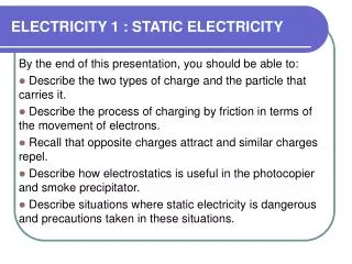
Electric charges • There are two types of electric charges:Charges of the same type repel. Charges of different types attract. • Benjamin Franklin named the two types of charges as “positive” and “negative”. • Electric charge is a conserved quantity. • Electric charge is measured in coulombs (C). They are quantized in multiples of the fundamental charge.One fundamental charge is 1.60 × 10⁻¹⁹ C. • Charge is intrinsic to some subatomic particles:Each proton has +1 fundamental charge.Each electron has –1 fundamental charge.
Charge transfers • An object’s net chargeis the sum of all its individual charges. Net charge always tends to be zero or nearly zero. • An electrically neutral object contains as many “+” charges as “–” charges. Its net charge is therefore zero. • Contact (or rubbing) can transfer electrons between objects. One object gains electrons and becomes negatively charged. The other object loses electrons and becomes positively charged. • Example: A dryer charges clothes via the rubbing effects. Therefore clothes tend to cling or repel.
Coulomb’s law • Two charges push or pull on one another with electrostatic forces that are equal in magnitude but opposite in direction. • Coulomb’s law:The electrostatic forces between two charges are proportional to the amount of each charge, and are inversely proportional to the square of the distance between the two charges:
Voltage • Charge has electrostatic potential energy(EPE). • Voltage measures the electrostatic potential energy per unit charge: • Voltage is measured in volts (1 volt = 1 joule/coulomb). • Separating opposite charges takes work. This work increases the voltage difference between the two charges. • Positive charge at high voltage can release EPE by moving to lower voltage. Negative charge at low voltage can release EPE by moving to higher voltage.
Electric polarization • When a negatively charged sock is put close to the wall, the wall’s positive charges shift toward the sock, and the wall’s negative charges shift away from it. This is called Electric polarization. • Opposite charges are nearer and attract strongly. Like charges are farther and repel less strongly.Therefore the charged sock clings to the polarized wall. Demo 1:Paper fragments Demo 2:A balloon Demo 3:Running water Demo 4:A homemade electroscope
Read: Ch10: 1 • Homework 12-13: Writing a paper • Please write a paper of about 3-4 pages, describing and analyzing the operation of a physics-related technology used in our everyday life. • Please use your own words. • Please use the fundamental laws of physics to explain the technology. • Please discuss the impact of the technology on our society and your own experiences related to the technology. • Due: December 6
Electric circuit of a flashlight • A steady current flow requires a loop path of conductor, which is called an electric circuit, because charge mustn’t accumulate anywhere. • In a flashlight, the electric circuit is closed when the switch is turned on. The circuit is open when the switch is turned off. • When the switch is on, electrons flow around this loop counterclockwise.
A “short” circuit is dangerous A short circuitis formed when there is little electric resistance in a powered loop. It occurs mostly by accident. A short circuit is dangerous because a huge amount of electric energy is released into thermal energy in a sudden.
Electric current • Electric currentis the rate of charge transfer, that is, the amount of electric charge passing a certain point per unit of time. • Current is measured in amperes (A).1 ampere = 1 coulomb/second. • In a flashlight, the electric current flows from the batteries through a wire to the light bulb filament. The current then returns through another wire back to the battery. Demo:Electric current
Ohm’s law • Electric currents experience voltage drops while passing through wires, filaments, and other conductors. • Ohm’s law:In ordinary electrical conductors, the current is proportional to the voltage drop: • Resistance is a characteristic of the conductor. It is measured by ohms(W). 1 ohm = 1 volt/ampere.
Electric power • Electric poweris the rate of energy transfer, that is, the electric energy transferred per unit of time. • This equation applies to both the battery and the filament of the light bulb. However, batteries provide electric power, while light bulbs consume electric power. • Electric power is measured in watts.1 watt = joules/second = 1 volt·ampere.
Questions: A flashlight uses two D-type batteries, each has a voltage of 1.5 V. How much is the voltage drop on the light bulb? If the current flowing around the circuit is 2 ampere, how much power does the electric bulb consume? How much is the resistance of the filament of the light bulb?
Batteries • A battery is one or more electrochemical cells that are used to convert stored chemical energy into electrical energy. • A battery has two terminals, the positive (+) and the negative (-). • Batteries are specified by their voltages, measured by volts (V). E.g., an AA battery has a voltage of 1.5 V. Symbol
Resistors • A resistor is an electronic component that is used to resist the electric current. It produces a voltage drop that is proportional to the electric current. • A resister has two terminals, which are usually not necessary to be distinguished. • Resistors are specified by their resistance, measured by ohms (W). There are many values of resistance available (e.g., 0.1 W −1 MW). Symbols
Electronic color code • The electronic color code is used to indicate the values of electronic components, commonly for resistors. Exercise: Mnemonics: Boys better remember our young girls become very good wives.
Capacitors • A capacitor consists of two conducting plates and an insulator that separates those plates. • The capacitor can accumulate equal but opposite charges on its plates. It develops a voltage difference between its plates and stores electrostatic potential energy. • Capacitors are specified by their capacitance,measured by Faraday (F). 1 F = 1 Coulomb/Volt. Symbol
Diodes • Three different electrical behaviors: • Metals can carry current in any direction. • Insulators can’t carry current. • A diode is a two-terminal electronic component that conducts electric current in only one direction. • When a voltage drop is applied on the forward direction, the diode conducts electric current. When the voltage drop is on the reverse direction, the diode blocks electric current. Symbol
Transistors • A transistor is a semiconductor device. It usually has three terminals for connection to a circuit. • In a transistor, a voltage or current applied to one pair of terminals (B-E) changes the current flowing through another pair of terminals (C-E). Therefore transistors are usually used to amplify or switch electronic signals. Symbol
Solderless breadboard • A solderless breadboardis a construction base for a prototype electronic circuit.