Download
1 / 36
360 likes | 445 Views
Induced radioactivity in the target station and in the decay tunnel from a 4 MW proton beam. S.Agosteo (1) , M.Magistris (1,2) , Th.Otto (2) , M.Silari (2) (1) Politecnico di Milano; (2) CERN. Introduction. In a Neutrino Factory, neutrinos result from the decay of high-energy muons

E N D
Induced radioactivity in the target station and in the decay tunnel from a 4 MW proton beam S.Agosteo(1), M.Magistris(1,2), Th.Otto(2), M.Silari(2) (1) Politecnico di Milano; (2) CERN
Introduction • In a Neutrino Factory, neutrinos result from the decay of high-energy muons • These muons are themselves decay product of a pion beam generated by the interaction of a high-intensity proton beam with a suitable target
Introduction There are two different ideas for producing a neutrino beam: • Muon storage ring • Neutrino super beam These results give some guide-lines, which are intended for both facilities
Introduction • An important aspect of a future Neutrino Factory is the material activation in the target system and its surroundings. • A first estimation of the production of residual nuclei has been performed by the Monte Carlo cascade code FLUKA
FLUKA simulations • A compromise between CPU time and precision: A simplified geometry DEFAULTS SHIELDIN, conceived for calculations for proton accelerators The new evaporation module is activated (EVAPORAT) The pure EM cascade has been disabled
An overview of the facility Top view Top view The facility consists of a target, two horns, a decay tunnel and a dump. It is shielded by 50 cm thick walls of concrete and is embedded in the rock.
Target and horns Protonbeam • A 4 MW, 2.2 GeV proton beam is sent onto the target with a flux of 1.1E16 protons/s. • A liquid mercury target is presently being considered, inserted in two concentric magnetic horns for pion collection and focusing.
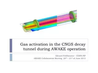
Decay tunnel The decay tunnel consists of a steel pipe filled with He (1 atm), embedded in a 50 cm thick layer of concrete Front view 60 m long Inner diameter of 2 m Thickness of 16 mm Cooling system (6 water pipes)
Rooms for maintenance • Two small rooms of 6 m2, filled with air, have been placed upstream of the magnetic horns for dose scoring • Two concentric magnetic horns • (300 kA, 600 kA) surround the target Top view
Rooms for maintenance • Two small rooms of 6 m2, filled with air, have been placed upstream of the magnetic horns for dose scoring • Two concentric magnetic horns • (300 kA, 600 kA) surround the target Side view
Beam dump Downstream of the decay tunnel, a dump consisting of: • An inner cylinder of graphitic carbon • An outer cylinder of polycristalline graphite • An iron shielding Side view
Surroundings • The whole structure (target, horn and decay tunnel) is embedded in the rock, which has been divided into 100 regions for scoring the inelastic interaction distribution
Surroundings • The whole structure (target, horn and decay tunnel) is embedded in the rock, which has been divided into 100 regions for scoring the inelastic interaction distribution
Horn • Material: ANTICORODAL 110 alloy (Al 96.1%) • Irradiation time: six weeks • Specific activity (Bq/g) at different cooling times
Steel pipe • Material: steel P355NH (Fe 96.78%) • Average values for the whole pipe (60 m long) • 10 years of operation • Operational year of 6 months (1.57*107 s/y) • Specific activity (Bq/g) Steel pipe
Steel pipe: 24 regions for scoring • In order to obtain the spatial distribution of stars and induced radioactivity, the steel pipe has been divided into 24 regions 1.6 cm thick 5 m long
Steel pipe, after 10 years of operation 1 year of cooling
Steel pipe, central part • Induced activity (Bq/g) in the central part of the pipe and multiples of EL (Exemption Limits) calculated with the addition rule
Concrete • The target system is shielded by 50 cm thick walls of concrete • Specific activity (Bq/g) after 10 years of operation, operational year of 6 months Concrete around the tunnel Air He Concrete around the horn
Earth around the decay tunnel The distribution of the induced radioactivity in the earth has been obtained: • Dividing the earth into six concentric layers (1 m thick)
Earth around the decay tunnel The distribution of the induced radioactivity in the earth has been obtained: • Dividing each layer into twelve regions
Earth, after 10 years of operation 1 year of cooling Exponential fit at 10 m,35 m,55 m from the target. Lambda=0.86 (+/-2.2%)
Conclusions • Every year of operation, 4 horns become highly radioactive and require a long term deposit, e.g. underground close to the facility • After 10 years of operation, the steel pipe in the decay tunnel, the concrete and a 2 m thick layer of earth have to be treated as radioactive waste • Outside this “hot region”, after 10 years of operation and 20 years of cooling the induced radioactivity in the earth goes below the Swiss exemption limit
Future work Based on these simulations, estimation of the dose-equivalent rate due to • The horn • The steel pipe • The concrete for maintenance, dismantling and radiation-protection issues