Download
1 / 45
450 likes | 632 Views
Seminars and Discussions on the Radio Astronomy in Asia Pacific Region. RAFCAP Meeting Kuala Lumpur May 19 –20, 2004. Radio Astronomy in India. N. Udaya Shankar RRI T.L. Venkatasubramani NCRA. Introduction. Radio Astronomy in India began with the installation of 32 dishes of 1.8 m dia.

E N D
Seminars and Discussions on the Radio Astronomy in Asia Pacific Region. RAFCAP Meeting Kuala Lumpur May 19 –20, 2004
Radio Astronomy in India N. Udaya Shankar RRI T.L. Venkatasubramani NCRA
Introduction • Radio Astronomy in India began with the installation of 32 dishes of 1.8 m dia. • 1965 Kalyan near Bombay (Present Mumbai)…..G.Swarup • The latest installation: GMRT Pune near Bombay 30 Antennas of 45m dia Spread over 25Km Freqs: 150, 325, 610/235, 1000-1420 MHz
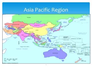
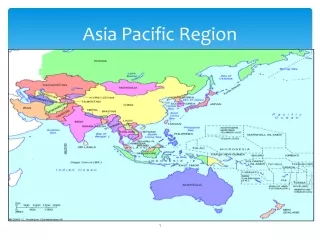
Radio Astronomy Installations in India TIFR: Tata Institute of Fundamental Research RRI: Raman Research Institute
Radio Astronomy Installations in India IIA: Indian Institute of Astrophysics PRL: Physical Research Laboratory
Introduction • Ooty Radio Telescope 327 MHz • 10.4 m mm wave Telescope mm wave • Gauribidanur Radio telescope 34.5 MHz • Mauritius Radio Telescope 150 MHz • GMRT 150-1400 MHz • Future Installations GMRT upgrades Comapct Cluster / 500-8000 MHz Participation in SKA
Main Focus Of Indian RA • Low Frequency Meter and Decameter wavelengths (Exception of 10.4m telescope) • India Offers Unique advantages 1. Lesser RFI than west 2. Labour Intensive nature 3. Coverage of both N and S Hemispheres 4. Bootstrapping---- One Experience leading to another
Is it Scientifically rewarding to have such a focus ? • Primordial Hydrogen • Oldest and diffuse electrons….Source Evolution
Pulsars • Sub-luminous matter in the early universe • Deuterium Abundance • Recombination lines of carbon Study of atoms which are almost of a micron size……n=574.
ORT • Parabolic Cylinder 530m 30m • 1100 SS wires 0.38mm dia • Built on a hill with a slope of 11º • Equal to the latitude of the observatory • ORT equatorially mounted telescope • Effective collecting area 8000 m2 • Eq of a 138m Dish
Cosmological Evolution • Ooty Days in 1970 • Steady State Vs Evolving Universe • Ooty Observations Angular Size -Flux density Observations Using Lunar Occultations • 1 to 10 Arcsec ..unachieved in those days for a large sample of weak sources • Number density of Radio Sources higher at earlier epochs but had smaller linear sizes • A very strong support for evolution
Interplanetary Scintillations • Twinkling of stars • Extragalactic sources…..IPM • Solar wind studies Sweeping past the earth 400 Km / Sec • Source Structures • Space Weather Studies
RRI 10.4m Telescope • The first mm wave telescope of India • Late 1970’s …75 micron surface accuracy was an achievement Sio Masers 86.2 GHz…..CO emission 115.3 A study of Molecular clouds …After effects of star formation ….Condensates forming cometary globules…..Gum Nebula. • 6.7 GHz Methanol Maser Survey…Galactic Plane
Images • Sky Coverage (1 ) Right Ascension: 18 to 24 hrs Declination : -700 to -100 • Frequency : 151.6 MHz • Resolution : 4'x4' • Integration time : 4 s • Bandwidth : 1 MHz • Noise(achieved) : 100-350 mJy/beam (expected) : 50-120 mJy/beam • Almost complete uv coverage
Deconvolution of MRT Images • A deconvolved image of a small region of the sky seems satisfactory. • The Problems of PSF changes due to non-coplanar have already been addressed. • Chromatic Aberration effects are being included. = 0.05 upto 3 Hogbom clean Raw Image Deconvolved Image
GMRT Y 18 Arm antennas ---25 Longest Baseline 12 CSQ ant 1.1 SqKm
Current PerformanceMeasured System Parameters *~ x20 with only the Central Square ** ~x2, with only the Central Square Source: The Giant Meterwave Radio Telescope S. Ananthakrishnan and A. Pramesh Rao. Multicolour Universe Conference, 2001
Current PerformanceAstronomical Usage • An independent GMRT Time Allocation Committee (GTAC), appointed by the NCRA Management Board issues periodic calls for proposals to observe with the GMRT, rates the proposals for scientific merit and allots time. • 1st Cycle: Jan – May 1992; About 1600 hours of time has been allotted per cycle. • Time Allotment for ~70 proposals for the 4th GTAC Cycle in progress • 26 publications from GMRT (end-2002 status) • We are able to go down to 30-40 microJansky flux density level. • A point source map with 0.11 million dynamic range has been recently made.
3C236 Red shift=.09 Dist=300 Mpc V=20,000Km/s
New Pulsar 0514-40A • In Globular Cluster NGC 1851 • Most eccentric orbit known, e=0.89 • Period=4.99 (common Tens of millisecs) • Companion Mass > 0.9 Solar Mass • First Pulsar Discovered by GMRT
GMRT Specifications Parabolic Reflector Diameter 45m Focal Length 18.54 m Physical aperture 1590 m2 Sensitivity of single dish 0.3 K/Jy Feed Support Quadripod Mounting Altitude-azimuth Elevation Limits Software Limit 17-90 degrees Hardware Limit 15-110 degrees Azimuth Limits Software Limit -265 to +265 degrees Hardware Limit -270 to +270 degrees Slew rate Azimuth 30 degree/minute Elevation 20 degree/minute Design wind speeds Operation up to 40 km/h (3 sec peak at 10 m height) Slew up to 80 km/h Survival 133 km/h Size of wire mesh of 20x20 mm, outer 1/3 area reflecting surface 15x15 mm, middle 1/3 area 10x10 mm, inner 1/3 area Maximum rms surface errors, 20 mm, outer 1/3 area at wind speed of 40 kmph 12 mm, middle 1/3 area 08 mm, inner 1/3 area Tracking and pointing accuracy 1'rms at wind speeds of < 20 km/h
Problem areas for the future • Mobile phones (2004-05?) -- Rich village with turn-over of ~$500,000 per year in grapes (Note: Excellent champagne! ) and onion • 4-lane Super Highway (2007??) -- 1 vehicle/ 3 minutes in 1985 with 2 lanes -- 3 vehicles/ 1 minute in 2004 with 2.25 lanes! • New International Airport at Chakan, about half-way between Pune and Narayangaon (2010???) • New Railway line linking Pune and Nashik, probably crossing through the array (2015????) • An intensive Interference Monitoring is under way Joardar etal
Why should we take up A New Cluster Antenna Array At GMRT Campus?? • Certain science drivers • Projection of this as India’s initiative in SKA related activities • Attempt to get into cm-wavelengths which would be of common interest to Radio Astronomers and ISRO
Need for creating a pool of young talented engineers interested in RA • A Platform to test ideas and instruments meant for GMRT- Upgrade • Important drivers for initiating a collaborative project
Scientific Goals • Compact Cluster to measure short spacings • Profitable Usage of a Modest Collecting Area Rather than Scattering a Smaller Number Of Antennas For Higher Angular Resolution. • Low Surface Brightness Radio Sources
A possible remedy.. Nine- 12m antennas in reuleuxaux configuration placed within the central square C9-C2 = C5-D0
24 antennas in a reuleuxaux triangle 24 antennas in a reuleuxaux triangle
Conclusion • Definitely a cluster added to GMRT will improve its low spatial frequency coverage • What is optimum ? • Where to locate it ? • What should be the antenna sizes ? • Effects of shadowing ? A lot more interesting questions…..