Download
1 / 18
220 likes | 454 Views
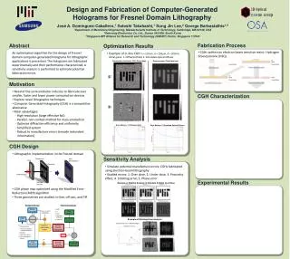
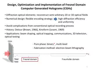
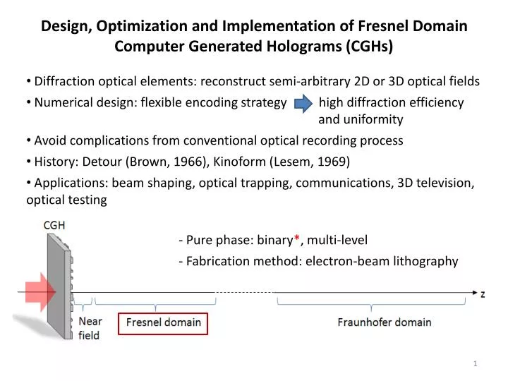
Design, Optimization and Implementation of Fresnel Domain Computer Generated Holograms (CGHs). Diffraction optical elements: reconstruct semi-arbitrary 2D or 3D optical fields

E N D
Design, Optimization and Implementation of Fresnel Domain Computer Generated Holograms (CGHs) • Diffraction optical elements: reconstruct semi-arbitrary 2D or 3D optical fields • Numerical design: flexible encoding strategy high diffraction efficiency and uniformity • Avoid complications from conventional optical recording process • History: Detour (Brown, 1966), Kinoform (Lesem, 1969) • Applications: beam shaping, optical trapping, communications, 3D television, optical testing • Pure phase: binary*, multi-level • Fabrication method: electron-beam lithography
Motivation • Increasing demand for smaller sized features, large working area semiconductor devices (e.g. LCD manufacture) need novel lithographic methods • CGHs promising candidates for replacing conventional 2D or 3D lithographic techniques • Key advantages: • Depth of focus control • Robust design • Standard fabrication • Simple optical setup • Cost effective • Non-contact • Parallel exposure • High resolution • Large working area • 2D or 3D patterning In-line CGH Lithography Final Device Processing
Problem Definition • Performance of CGHs depends primarily on optimization algorithm and fabrication method • Previous work: X-ray (Jacobsen, 1992), UV (Wyrowski, 2001), EUV (Isoyan, 2006) • Local search methods: inefficient, sensitive to initial point, get trapped at local minima • Current multi-search schemes: optimize small size CGHs Back-propagation CGH Plane Reconstruction Plane Encoding CGH Plane Reconstruction Plane Free parameter Desired Pattern Inverse Problem
Encoding Process CGH Plane CGH: encoded signal Problem Definition • Performance of CGHs depends primarily on optimization algorithm and fabrication method • Previous work: X-ray (Jacobsen, 1992), UV (Wyrowski, 2001), EUV (Isoyan, 2006) • Local search methods: inefficient, sensitive to initial point, get trapped at local minima • Current multi-search schemes: optimize small size CGHs Forward-propagation CGH Plane Reconstruction Plane Decoding Reconstruction Plane CGH Plane Photoresist Exposure Final Pattern Inverse Problem
Reduced Complexity Hybrid Optimization Algorithm (RCHOA) • Efficient optimization of Fresnel binary and multi-level phase CGHs • Reduce problem complexity by introducing: Local Diffuser Phase Elements (LDPE) and Local Negative Power Elliptical Phase Elements (LNPEPE) masks • Optimize reduced subset of variables • Key features: • Multi-point parallel search • Robust: insensitive to initial points • Flexible choice of encoding signal • Reduced complexity • Optical efficient results • Computationally efficient: GPU implementation
Off-Axis Geometry System Geometries TIR Geometry In-Line Geometry*
Local Diffuser Phase Elements Mask • Maximize information transfer: amplitude (reconstruction plane) to phase (CGH plane) • Step 1: decompose desired pattern into Nbp binary patterns • Step 2: assign local diffuser phase element to each pattern • Diffusivity of qth element controlled by: and • LDPE mask: Mask Decomposition CGH Plane Reconstruction Plane Phase Binary Phase CGH Desired Amplitude Mask LDPE Mask Random matrix x Fresnel Back-Propagation Binary function Amplitude Multi-level Each element has different diffusivity • Reduced number of DOF:
Local Negative Power Elliptical Phase Elements Mask • Maximize information transfer: amplitude (reconstruction plane) to phase (CGH plane) • Step 1: decompose desired pattern into Nbp binary patterns • Step 2: apply LNPEPE to each pattern • Controlled parameters: • LNPEPE mask: CGH Plane Reconstruction Plane Binary pattern center coordinates Phase Desired Amplitude Mask LNPEPE Mask Truncation window Binary function x Fresnel Back-Propagation Amplitude • Reduced number of DOF: Negative power elliptical phase
Genetic Algorithms Block • Multi-point optimization scheme • Inspired in biological evolution: “survival of the fittest” • Reduced complexity allow optimizing large populations • Individual: • or Global minimum The MathWorksTM
MER Block • Local search, iterative optimization method • Refine solution: fast convergence • Compare results with: diffracted field (DF) and simulated optically recorded hologram (SORH) encoding strategies
Error Metrics Photoresist Contrast Curve • Four considered error metrics • Choice of error metric is application dependent - Mean square error: bias estimator ( and ) dose Amplitude Constraint - Diffraction efficiency Signal Power Effective efficiency inside pattern Input power Signal Power Inside Hsize (G. Zhou, et al., 2000) - Additional metrics: L1 (bias) and normalized cross-correlation (similarity), hybrid
Reconstruction from Multi-Level CGH at Photoresist Plane (Before Exposure) Intensity Optimized LDPE Mask Phase Map: Optimized Binary CGH Reconstruction from Binary CGH at Photoresist Plane (Before Exposure) Intensity Optimization Results Main Parameters: • Optimization example: • - binary phase CGH: resolution target - LDPE encoding strategy Desired Pattern Convergence MER Block Convergence GA Block Intensity Intensity
Optimization Results • Optimization example: • - binary phase CGH: resolution target - LDPE encoding strategy • Sensitivity Analysis: problem parameters (e.g. cross-over fraction, population size, etc.) • Parallel implementation on graphic processing unit: speedup >180X • - GPU computational time: 4.47 hours • - CPU estimated time: 16.48 days! Comparison of Encoding Strategies After GAs Block: Multi-Level CGH
Extending the Depth of Focus • Extend DOF: tolerate potential axial misalignments during exposure process • Modify RCHOA to impose constraints at multiple planes • Regular DOF: Multiple Plane Constraint Error Comparison: Binary CGH Extended DOF CGH Extended:
CGH Fabrication Fabrication Process • Fabricated using electron-beam lithography • Binary phase CGH • Resist: Hydrogen Silsesquioxane (HSQ) E-beam Patterning Fused Silica Aluminum Remove Aluminum & Develop HSQ HSQ Scanning Electron Microscope Image of Fabricated Sample 50μm
Characterization of Fabricated CGHs • Implemented methods: evaluation algorithm*, optical characterization*, exposure test • Evaluation algorithm: analyze fabricated CGH 2D error map (correct over/under dose) Stitched Binarized Fabricated CGH Block Diagram of Evaluation Algorithm 2D Error Map
Characterization of Fabricated CGHs • Implemented methods: evaluation algorithm*, optical characterization*, exposure test • Optical characterization: measure reconstructed intensity Optical Setup: Coherent Illumination Measured Reconstructed Intensities Binary CGH: DF Encoding Strategy Binary CGH: Diffuser Encoding Strategy • Fabricated CGHs not fully optimized • Eliminate speckle using partial coherence illumination 100μm
Sensitivity Analysis • Estimate and assist in the correction of potential fabrication errors • Considered errors: e-beam over/under dose, proximity effect, uniform/nonuniform phase, stitching and positional errors Dilation Test: Over Dose Error Stitching Error Analysis MSE Offset Distance