Download
1 / 28
290 likes | 294 Views
Status and Prospects of Nuclear Fusion Using Magnetic Confinement. Hartmut Zohm Max-Planck-Institut für Plasmaphysik, Garching, Germany. Invited Talk given at DPG Frühjahrstagung, AKE, Berlin, 17.03.2014. Nuclear Fusion using Magnetic Confinement Fusion Roadmap and Roadmap Elements

E N D
Status and Prospects of Nuclear Fusion Using Magnetic Confinement Hartmut Zohm Max-Planck-Institut für Plasmaphysik, Garching, Germany Invited Talk given at DPG Frühjahrstagung, AKE, Berlin, 17.03.2014
Nuclear Fusion using Magnetic Confinement • Fusion Roadmap and Roadmap Elements • The German Contribution • Summary andConclusions
Nuclear Fusion using Magnetic Confinement • Fusion Roadmap and Roadmap Elements • The German Contribution • Summary andConclusions
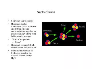
A simplistic view on a Fusion Power Plant Pout = 2-3 GWth (aiming at 1 GWe) Pin = 50 MW (initiate and control burn) The ‚amplifier‘ is a thermonuclear plasma burning hydrogen to helium Centre of the sun: T ~ 15 Mio K, n 1032 m-3, p ~ 2.5 x 10¹¹ bar
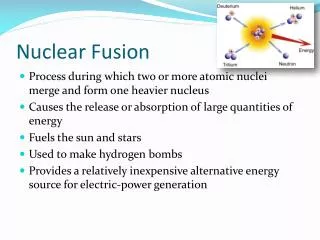
A bit closer look… Pout = 2-3 GWth (aiming at 1 GWe) Pin = 50 MW (initiate and control burn) 3.5 MeV 14.1 MeV a-heating wall loading Fusion reactor: magnetically confined plasma, D + T → He + n + 17.6 MeV Centre of reactor: T = 250 Mio K, n = 1020 m-3, p = 8 bar
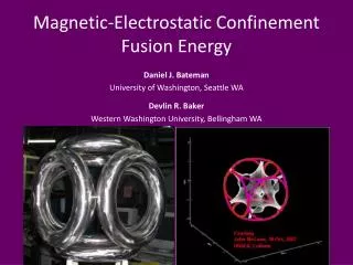
Magnetic confinement The goal is to generate and sustain a plasma of 25 keV and 1020 m-3 This can be done in a toroidal system to avoid end losses helical magnetic field lines to compensate particle drifts
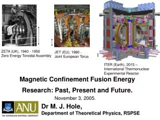
Plasma can be confined in a magnetic field 'Stellarator': magnetic field exclusively produced by coils Example: Wendelstein 7-X (IPP Greifswald)
Plasma can be confined in a magnetic field 'Tokamak': poloidal field component from current on plasma Simple concept, but not inherently stationary! Example: ASDEX Upgrade (IPP Garching)
The promise of fusion power plants • Supply of base load electricity (not dependent on externals) • complementary to stochastic sources like wind or solar • Sustainable energy source (fusion fuel available for many 1000s of years) • Deuterium e.g. from sea water • T will be bred from Li in the innermost part of the reactor • Fusion energy will be environmentally friendly • no CO2 emission • no uncontrolled chain reaction • radioactive waste (= structural materials) relatively short-lived
The road to Fusion Energy holds many challenges • Fusion plasma physics • heat insulation of the confined plasma • exhaust of heat and particles • magnetohydrodynamic (MHD) stability of configuration • self-heating of the plasma by fusion born a-particles • Fusion specific technology • plasma heating • fuel cycle including internal T-breeding from Li • development of suitable materials in contact with plasma
The road to Fusion Energy holds many challenges • Fusion plasma physics • heat insulation of the confined plasma • exhaust of heat and particles • magnetohydrodynamic (MHD) stability of configuration • self-heating of the plasma by fusion born a-particles • Fusion specific technology • plasma heating • fuel cycle including internal T-breeding from Li • development of suitable structural and first wall materials
Nuclear Fusion using Magnetic Confinement • Fusion Roadmap and Roadmap Elements • The German Contribution • Summary andConclusions
A step-ladder of fusion experiments to ITER ASDEX Upgrade (IPP) 1.65 m 14 m3 1.5 MW (D-T equivalent) JET (EU) 3 m 80 m3 ~ 16 MWth (D-T) ITER 6.2 m 800 m3 ~ 400 MWth (D-T) Major Radius Volume Fusion Power The machine has to be big in order to have sufficient heat insulation (tE)
The step from ITER to DEMO • ITER = proof of principle for dominantly a-heated plasmas • DEMO = proof of principle for reliable large scale electricity production • DEMO must be larger: 6.2 m 8.5 m, 400 MW ~ 2 GW • This brings new challenges for physics (and technology) • higher density, higher pressure (stability!) • higher power density (Pfus~R3, Atarget~ R) • need for long pulse or steady state • (tokamak presently a pulsed system) • We will not run out of work in near future! • also alternative magnetic confinement • concepts must be studied Tokamak (ASDEX Upgrade, JET, ITER)
The step from ITER to DEMO • ITER = proof of principle for dominantly a-heated plasmas • DEMO = proof of principle for reliable large scale electricity production • DEMO must be larger: 6.2 m 7.5 m, 400 MW ~ 2 GW • This brings new challenges for physics (and technology) • higher density, higher pressure (stability!) • higher power density (Pfus~R3, Atarget~ R) • need for long pulse or steady state • (tokamak presently a pulse system) • We will not run out of work in near future! • also alternative magnetic confinement • concepts must be studied • Example: W7-X stellarator (IPP Greifswald) Stellarator (W7-X)
The Role of Stellarators in the EU Roadmap • Using technology developed on a tokamak DEMO, stellarator can be candidate for a Fusion Power Plant in the 2050s
Nuclear Fusion using Magnetic Confinement • Fusion Roadmap and Roadmap Elements • The German Contribution • Summary andConclusions
German Fusion Programme: Combined Expertise Stellarator Physics and Technology Plasma Wall Interactions Fusion Tokamak Technology Physics and Technology Unique combination of physics and technology Coordinated effort through ‚German DEMO Working Group‘
German DEMO Working Group: Roadmap Elements 7 Roadmap Elements thatneedtobetackled in any Roadmap havebeenidentified • RE1: Consistent Tokamak Scenarios • RE2: Consistent Stellarator Scenarios • RE3: EnduringExhaustof Power andParticles • RE4: Safety – Public Accpetanceand Licensing • RE5: Sustainability – Tritium Self-sufficiency & Low Activation • RE6: EconomicViability – Efficiency / Reliability / Availability • RE7: Stellarator Specific Technology The followingexampleshighlighthowthese Roadmap Elements bring togethertheexpertiseof Fusion Research in Germany
KIT, 1MW, 105 – 165 GHz SP prototype Mode for 237 GHz coaxgyrotron Brewster-angle technology (CVD Diamond window) Tokamak Scenarios (RE1) / Economic Viability (RE6) • Realistic fully noninductive scenario may require substantial PCD • Sets the goals for future gyrotron development at f > 200 GHz • Issues of controllability must be incorporated from the start TE49,29 Simulation of fully noninductive DEMO scenario
Exhaust of Power and Particles (RE3) • Combined physics / technology requirements: P/Rsep 15 MW/m, Ptarget 5 MW/m2, Te,div 5 eV • Optimised technology solution may be He-cooled divertor W-divertor in ITER He-cooled divertor for DEMO
Stellarator Scenarios (RE2) & Technology (RE7) Modular Coils / Blanket Plasma Geometry Island Divertor • Stellarator specificsare incorporated into tokamak systemscodes • Critical elements in physicsandtechnology will beassessed Plasma geometry described by Fourier coefficients of LCFS obtained from VMEC. Model relates power crossing separatrix to effective wetted area to estimate heat load. Existing coil design of Helias 5-B builds model basis which is scaled as input.
Stellarator Scenarios (RE2) & Technology (RE7) Modular Coils / Blanket Plasma Geometry Island Divertor • Stellarator specificsare incorporated into tokamak systemscodes • Critical elements in physicsandtechnology will beassessed Plasma geometry described by Fourier coefficients of LCFS obtained from VMEC. Model relates power crossing separatrix to effective wetted area to estimate heat load. Existing coil design of Helias 5-B builds model basis which is scaled as input.
Stellarator Scenarios (RE2) & Technology (RE7) Modular Coils / Blanket Plasma Geometry Island Divertor Plasma geometry described by Fourier coefficients of LCFS obtained from VMEC. Model relates power crossing separatrix to effective wetted area to estimate heat load. Existing coil design of Helias 5-B builds model basis which is scaled as input. • Stellarator specifics are incorporated into tokamak systems codes • Critical elements in physics and technology will be assessed
Nuclear Fusion using Magnetic Confinement • Fusion Roadmap and Roadmap Elements • The German Contribution • Summary andConclusions
Conclusions Significant progress of understanding in all basic areas of Nuclear Fusion research by developing plasma physics and technology base • core plasma parameters sufficient for generation of fusion energy • technical systems mature for controlling thermonuclear plasma Nuclear Fusion research is ready for the next step • ITER will be built in an international effort • will allow qualitatitvely new studies: exploring plasmas with dominant a-heating The step to DEMO and a Fusion Power Plant builds on ITER but must be prepared in due time • adress physics and technology in an integrated way • bring in the stellarator line in a consistent manner