Download
1 / 71
710 likes | 718 Views
This article provides a recap of the functions of the data link layer, including framing, media access control, error detection, reliable delivery, and flow control. It also discusses point-to-point and broadcast LAN protocols, such as TDMA, FDMA, CDMA, Bluetooth, Token Ring, and Ethernet. Readings from the textbook are included.

E N D
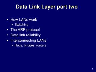
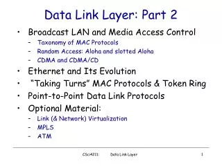
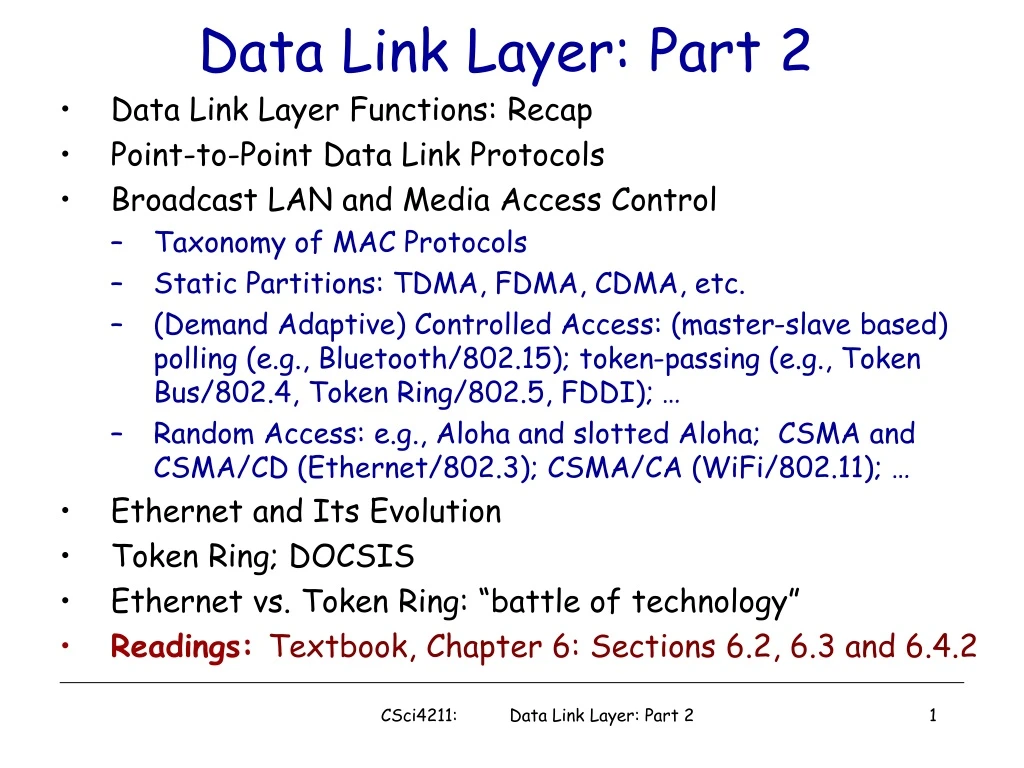
Data Link Layer: Part 2 • Data Link Layer Functions: Recap • Point-to-Point Data Link Protocols • Broadcast LAN and Media Access Control • Taxonomy of MAC Protocols • Static Partitions: TDMA, FDMA, CDMA, etc. • (Demand Adaptive) Controlled Access: (master-slave based) polling (e.g., Bluetooth/802.15); token-passing (e.g., Token Bus/802.4, Token Ring/802.5, FDDI); … • Random Access: e.g., Aloha and slotted Aloha; CSMA and CSMA/CD (Ethernet/802.3); CSMA/CA (WiFi/802.11); … • Ethernet and Its Evolution • Token Ring; DOCSIS • Ethernet vs. Token Ring: “battle of technology” • Readings: Textbook, Chapter 6: Sections 6.2, 6.3 and 6.4.2 CSci4211: Data Link Layer: Part 2
Some terminology: hosts and routers are nodes (bridges and switches too) communication channels that connect adjacent nodes along communication path are links wired links wireless links LANs (local area networks) layer 2 PDU (“packet”) referred to as frame, which encapsulates a layer-3 packet, e.g., an IP datagram “link” Data Link Layer: Basic Functions Recap CSci4211: Data Link Layer: Part 2
What Does Data Link Layer Do? Data link layer has responsibility of transferring frames from one node to adjacent node over a single link • An IP packet from host A to host B may traverses different links using different data link protocols • e.g., Ethernet on first link, frame relay on intermediate links, 802.11 on last link • Each link protocol provides different services • e.g., may or may not provide reliable data delivery • Different link protocols are not inter-operable! • IP packets are encapsulated/decapsulated with appropriate data link protocol header over each link • IP protocol and IP routers glue the links (“physical networks”) together and provide end-to-end data delivery! CSci4211: Data Link Layer: Part 2
Data Link Layer Functions • Framing • sender (transmitter): encapsulate datagram into frame, adding header, trailer, transmit frame • receiver: detect beginning of frames, receive frame, decapsulate frame, stripping off header, trailer • Link Access (Media Access Control) • determine whether it’s Okay to transmit over the link • particularly important when link shared by many nodes • also an issue over “half-duplex” point-to-point link (why?) • need media access control (MAC) • “physical addresses” identify sender/receiver on a link! • particularly important when link shared by many nodes, while over point-to-point link, not necessary • “physical addresses” often referred to as “MAC” addresses • different from IP addresses (which are logical & global)! CSci4211: Data Link Layer: Part 2
Other Data Link Layer Functions • Error Detection (commonly implemented) • errors caused by signal attenuation, noise, etc. • sender computes “checksum”, attaches to frame • receiver detects presence of errors by verifying “checksum” • drops corrupted frame, may ask sender for retransmission • Commonly used “checksum”: cyclic redundancy code (CRC) • Reliable Delivery between adjacent nodes (optional) • using, e.g., go-back-N or selective repeat protocol • seldom used on low bit error link (fiber, some twisted pair) • wireless links: high error rates • Q: why both link-level and end-end reliability? • Error Correction (optional) • receiver identifies and corrects bit error(s) without resorting to retransmission, using forward error correction (FEC) codes • Flow Control (optional) • negotiating transmission rates between two nodes CSci4211: Data Link Layer: Part 2
in each and every host link layer implemented in “adaptor” (aka network interface card NIC) or on a chip Ethernet card, 802.11 card; Ethernet chipset implements link, physical layer attaches into host’s system buses combination of hardware, software, firmware application transport network link link physical Where is the Link Layer Implemented? cpu memory host bus (e.g., PCI) controller physical transmission network adapter card CSci4211: Data Link Layer: Part 2
sending side: encapsulates datagram in frame adds error checking bits, rdt, flow control, etc. receiving side looks for errors, rdt, flow control, etc. extracts datagram, passes to upper layer at receiving side Adaptors Communicating datagram datagram controller controller receiving host sending host datagram frame CSci4211: Data Link Layer: Part 2
Ethernet Frame Structure sending adapter encapsulates IP datagram (or other network layer protocol packet) in Ethernet frame preamble: • 7 bytes with pattern 10101010 followed by one byte with pattern 10101011 • used to synchronize receiver, sender clock rates type dest. address source address data (payload) CRC preamble CSci4211: Data Link Layer: Part 1
Error Detection • EDC= Error Detection and Correction bits (redundancy) • D = Data protected by error checking, may include header fields • Error detection not 100% reliable! • protocol may miss some errors, but rarely • larger EDC field yields better detection and correction CSci4211: Data Link Layer: Part 1
Parity Checking Two Dimensional Bit Parity: Detect and correct single bit errors Single Bit Parity: Detect single bit errors 1 0 0 0 CSci4211: Data Link Layer: Part 1
Sender: treat segment contents as sequence of 16-bit integers checksum: addition (1’s complement sum) of segment contents sender puts checksum value into UDP checksum field Receiver: compute checksum of received segment check if computed checksum equals checksum field value: NO - error detected YES - no error detected. But maybe errors nonetheless? More later …. Internet Checksum (Review) • Goal: detect “errors” (e.g., flipped bits) in transmitted segment (note: used at transport layer only) CSci4211: Data Link Layer: Part 1
Checksumming: Cyclic Redundancy Check • view data bits, D, as a binary number • choose r+1 bit pattern (generator), G • goal: choose r CRC bits, R, such that • <D,R> exactly divisible by G (modulo 2) • receiver knows G, divides <D,R> by G. If non-zero remainder: error detected! • can detect all burst errors less than r+1 bits • widely used in practice (Ethernet, 802.11 WiFi, ATM) CSci4211: Data Link Layer: Part 1
CRC Example Want: D.2r XOR R = nG equivalently: D.2r = nG XOR R equivalently: if we divide D.2r by G, want remainder R D.2r G R = remainder[ ] CSci4211: Data Link Layer: Part 1
Point to Point Data Link Control • one sender, one receiver, one link: easier than broadcast link: • no Media Access Control • no need for explicit MAC addressing • e.g., dialup link, ISDN line • popular point-to-point DLC protocols: • PPP (point-to-point protocol) • HDLC: High level data link control • data link layer used to be considered “high layer” in protocol stack! CSci4211: Data Link Layer: Part 2
PPP Design Requirements [RFC 1557] • packet framing: encapsulation of network-layer datagram in data link frame • carry network layer data of any network layer protocol (not just IP) at same time • ability to demultiplex upwards • bit transparency: must carry any bit pattern in the data field • error detection (no correction) • connection liveness: detect, signal link failure to network layer • network layer address negotiation: endpoint can learn/configure each other’s network address CSci4211: Data Link Layer: Part 2
PPP Non-Requirements • no error correction/recovery • no flow control • out of order delivery OK • no need to support multipoint links (e.g., polling) Error recovery, flow control, data re-ordering all relegated to higher layers! CSci4211: Data Link Layer: Part 2
PPP Data Frame • Flag: delimiter (framing) • Address: does nothing (only one option) • Control: does nothing; in the future possible multiple control fields • Protocol: upper layer protocol to which frame delivered (eg, PPP-LCP, IP, IPCP, etc) CSci4211: Data Link Layer: Part 2
PPP Data Frame • info: upper layer data being carried • check: cyclic redundancy check for error detection CSci4211: Data Link Layer: Part 2
Byte Stuffing • “data transparency” requirement: data field must be allowed to include flag pattern <01111110> • Q: is received <01111110> data or flag? • Sender: adds (“stuffs”) extra < 01111110> byte after each < 01111110> data byte • Receiver: • two 01111110 bytes in a row: discard first byte, continue data reception • single 01111110: flag byte CSci4211: Data Link Layer: Part 2
Byte Stuffing flag byte pattern in data to send 0 11 1 1 1 1 0 0 11 1 1 1 1 0 flag byte pattern plus stuffed byte in transmitted data CSci4211: Data Link Layer: Part 2
PPP Link/Network Control Protocols Before exchanging network-layer data, data link peers must • configure PPP link (max. frame length, authentication) • learn/configure network layer information • for IP: carry IP Control Protocol (IPCP) msgs (protocol field: 8021) to configure/learn IP address CSci4211: Data Link Layer: Part 2
Multiple Access Links:MAC Protocols two types of “links”: • point-to-point • PPP for dial-up access • point-to-point link between Ethernet switch, host (PPPoE) • broadcast (shared wire or medium) • old-fashioned Ethernet • upstream HFC • 802.11 wireless LAN humans at a cocktail party (shared air, acoustical) shared RF (e.g., 802.11 WiFi) shared RF (satellite) shared wire (e.g., cabled Ethernet) CSci4211: Data Link Layer: Part 2
Broadcast LAN: Media Access Control • Broadcast LAN: single shared broadcast channel • two or more simultaneous transmissions by nodes: interference! • collision if node receives two or more signals at the same time • only one node can send successfully at a time! • How to share a broadcast channel? • Humans use multi-access protocols all the time Multiple Access Protocol • distributed algorithm that determines how nodes share channel, i.e., determine when node can transmit • communication about channel sharing must use channel itself! • what to look for in multiple access protocols: • synchronous or asynchronous • information needed about other stations • robustness • performance: access delay and throughput CSci4211: Data Link Layer: Part 2
MAC Protocols: a Taxonomy Three broad classes: • Channel Partitioning (static controlled access) • divide channel into smaller “pieces” (e.g., time slots -> TDMA, frequency->FDMA, code->CDMA) • allocate piece to node for exclusive use • “Demand Adaptive” Controlled Access: e.g., Polling or Taking Turns • tightly coordinate shared access to avoid collisions • Random Access • channel not divided, allow collisions • “recover” from collisions CSci4211: Data Link Layer: Part 2
Taxonomy of MAC Protocols CSMA/CA (WiFi/802.11) polling CSci4211: Data Link Layer: Part 2
Channel Partitioning MAC protocols: TDMA TDMA: time division multiple access • access to channel in "rounds" • each station gets fixed length slot (length = packet transmission time) in each round • unused slots go idle • example: 6-station LAN, 1,3,4 have packets to send, slots 2,5,6 idle 6-slot frame 6-slot frame 3 3 4 4 1 1 CSci4211: Data Link Layer: Part 2
Channel Partitioning MAC Protocols: FDMA FDMA: frequency division multiple access • channel spectrum divided into frequency bands • each station assigned fixed frequency band • unused transmission time in frequency bands go idle • example: 6-station LAN, 1,3,4 have packet to send, frequency bands 2,5,6 idle time frequency bands FDM cable CSci4211: Data Link Layer: Part 2
“Taking Turns” MAC protocols channel partitioning MAC protocols: • share channel efficiently and fairly at high load • inefficient at low load: delay in channel access, 1/N bandwidth allocated even if only 1 active node! “Demand-Adaptive” Controlled Protocols • Human analogy: • traffic control with green/red light • fixed time vs. adaptive time vs. no lights at all • (Master-Slave based) Polling: • e.g., in a classroom: I am the “master” ;-) • “Taking Turns” via token-passing: • e.g., a round-table panel with a single microphone CSci4211: Data Link Layer: Part 2
“Taking Turns” MAC Protocols Token passing: • distributed • control token passed from one node to next sequentially. • what is a token? a special control message • concerns: • token overhead • latency • single point of failure (token) Polling: • centralized • master node “invites” slave nodes to transmit in turn • concerns: • polling overhead • latency • single point of failure (master) master slaves CSci4211: Data Link Layer: Part 2
Token Ring Topology Using token-passing, nodes do not have to form a physical ring! E.g., token bus: all nodes connected via a bus, forming a logical ring!) CSci4211: Data Link Layer: Part 2
Token Release oken oken T T Frame Frame Release after Reception (used by Token Ring) Release after Transmission (used by FDDI) CSci4211: Data Link Layer: Part 2
Token Ring Performance • Efficiency with “release after reception” where • What is the efficiency with “release after transmission” ? CSci4211: Data Link Layer: Part 2
Random Access Protocols • When node has packet to send • transmit at full channel data rate R. • no a priori coordination among nodes • two or more transmitting nodes -> “collision”, • random access MAC protocol specifies: • how to detect or avoid collisions • how to recover from collisions (e.g., via delayed retransmissions) • Examples of random access MAC protocols: • ALOHA • slotted ALOHA • CSMA, CSMA/CD, CSMA/CA CSci4211: Data Link Layer: Part 2
Pure (unslotted) ALOHA • unslotted Aloha: simple, no synchronization • when frame first arrives • transmit immediately • collision can happen! • frame sent at t0 collides with other frames sent in [t0-1,t0+1] CSci4211: Data Link Layer: Part 2
Assumptions all frames same size time is divided into equal size slots, time to transmit 1 frame nodes start to transmit frames only at beginning of slots nodes are synchronized if 2 or more nodes transmit in slot, all nodes detect collision Operation when node obtains fresh frame, it transmits in next slot no collision, node can send new frame in next slot if collision, node retransmits frame in each subsequent slot with prob. p until success Slotted ALOHA CSci4211: Data Link Layer: Part 2
Pros single active node can continuously transmit at full rate of channel highly decentralized: only slots in nodes need to be in sync simple Cons collisions, wasting slots idle slots nodes may be able to detect collision in less than time to transmit packet Slotted ALOHA Success (S), Collision (C), Empty (E) slots CSci4211: Data Link Layer: Part 2
Suppose N nodes with many frames to send, each transmits in slot with probability p prob that 1st node has success in a slot = p(1-p)N-1 prob that any node has a success = Np(1-p)N-1 For max efficiency with N nodes, find p* that maximizes Np(1-p)N-1 For many nodes, take limit of Np*(1-p*)N-1 as N goes to infinity, gives 1/e = .37 Slotted Aloha efficiency Efficiency is the long-run fraction of successful slots when there’s many nodes, each with many frames to send At best: channel used for useful transmissions 37% of time! CSci4211: Data Link Layer: Part 2
Pure Aloha Efficiency P(success by given node) = P(node transmits) . P(no other node transmits in [p0-1,p0] . P(no other node transmits in [p0,p0+1] = p . (1-p)N-1 . (1-p)N-1 = p . (1-p)2(N-1) … choosing optimum p and then letting n -> infty ... = 1/(2e) = .18 Efficiency is even worse ! CSci4211: Data Link Layer: Part 2
0.4 0.3 Slotted Aloha 0.2 0.1 Pure Aloha 1.5 2.0 0.5 1.0 G = offered load = Np Performance of Aloha Protocols S = throughput = “goodput” (success rate) Can we do better with random access? CSci4211: Data Link Layer: Part 2
Carrier Sense Multiple Access • Aloha is inefficient (and rude): • doesn’t listen before talking • CSMA: Listen before transmit • Human analogy: don’t interrupt others! • If channel idle, transmit entire packet • If busy, defer transmission • How long should we wait? • Persistent vs. Nonpersistent CSMA • Nonpersistent: • if idle, transmit • if busy, wait random amount of time • p-persistent • If idle, transmit with probability p • If busy, wait till it becomes idle • If collision, wait random amount of time • Can carrier sense avoid collisions completely? CSci4211: Data Link Layer: Part 2
CSMA Collisions spatial layout of nodes collisions can still occur: propagation delay means two nodes may not hear each other’s transmission collision: entire packet transmission time wasted note: role of distance & propagation delay in determining collision probability CSci4211: Data Link Layer: Part 2
CSMA/CD (Collision Detection) CSMA/CD: carrier sensing, deferral as in CSMA • collisions detected within short time • colliding transmissions aborted, reducing channel wastage • human analogy: the polite conversationalist • talking while keep listening, stop if collision detected • How to detect collision? • easy in wired LANs: measure signal strengths, compare transmitted, received signals • difficult in wireless LANs: receiver shut off while transmitting CSci4211: Data Link Layer: Part 2
CSMA/CD: Illustration CSci4211: Data Link Layer: Part 2
Ethernet “Dominant” LAN technology today: • cheap $20 or less for 100 Mbps or even 1Gbps! • first widely used LAN technology • Simpler, cheaper than alternative technologies such as token ring LANs • Kept up with speed race: 10, 100, 1 Gbps, 10 Gbps, 40 Gbps, and now 100 Gbps Metcalfe’s Ethernet sketch CSci4211: Data Link Layer: Part 2
8 bytes 6 6 2 0-1500 4 Src Dest Type Data Preamble CRC addr addr 8 bytes 6 6 2 0-1500 4 Src Dest Length Data Preamble CRC addr addr Ethernet Frame Format DIX frame format Sending adapter encapsulates IP datagram (or other network layer protocol packet) in Ethernet frame IEEE 802.3 format • Ethernet has a maximum frame size: data portion <=1500 bytes • It has imposed a minimum frame size: 64 bytes (excluding preamble) If data portion <46 bytes, pad with “junk” to make it 46 bytes Q: Why minimum frame size in Ethernet? CSci4211: Data Link Layer: Part 2
Fields in Ethernet Frame Format • Preamble: • 7 bytes with pattern 10101010 followed by one byte with pattern 10101011 (SoF: start-of-frame) • used to synchronize receiver, sender clock rates, and identify beginning of a frame • Addresses: 6 bytes • if adapter receives frame with matching destination address, or with broadcast address (eg ARP packet), it passes data in frame to net-layer protocol • otherwise, adapter discards frame • Type: indicates the higher layer protocol, mostly IP but others may be supported such as Novell IPX and AppleTalk) • 802.3: Length gives data size; “protocol type” included in data • CRC: checked at receiver, if error is detected, the frame is simply dropped CSci4211: Data Link Layer: Part 2
Ethernet and IEEE 802.3 1-persistent CSMA/CD • Carrier sense: station listens to channel first • Listen before talking • If idle, station may initiate transmission • Talk if quiet • Collision detection: continuously monitor channel • Listen while talking • If collision, stop transmission • One talker at a time CSci4211: Data Link Layer: Part 2
1. Adaptor gets datagram from and creates frame 2. If adapter senses channel idle, it starts to transmit frame. If it senses channel busy, waits until channel idle and then transmits 3. If adapter transmits entire frame without detecting another transmission, the adapter is done with frame ! Signal to network layer “transmit OK” 4. If adapter detects another transmission while transmitting, aborts and sends jam signal 5. After aborting, adapter enters exponential backoff: after the mth collision, adapter chooses a K at random from {0,1,2,…,2m-1}. Adapter waits K*512 bit times and returns to Step 2 6. Quit after 16 attempts, signal to network layer “transmit error” Ethernet CSMA/CD Algorithm CSci4211: Data Link Layer: Part 2
Jam Signal: make sure all other transmitters are aware of collision; 48 bits; Bit time: .1 microsec for 10 Mbps Ethernet ;for K=1023, wait time is about 50 msec Exponential Backoff: Goal: adapt retransmission attempts to estimated current load heavy load: random wait will be longer first collision: choose K from {0,1}; delay is K x 512 bit transmission times after second collision: choose K from {0,1,2,3}… after ten collisions, choose K from {0,1,2,3,4,…,1023} Ethernet’s CSMA/CD (more) See/interact with Java applet on AWL Web site: highly recommended ! CSci4211: Data Link Layer: Part 2
IEEE 802.3 Parameters • 1 bit time = time to transmit one bit • 10 Mbps 1 bit time = 0.1 microseconds • Maximum network diameter <= 2.5km • Maximum 4 repeaters • “Collision Domain” • Distance within which collision can be detected • IEEE 802.3 specifies: worst case collision detection time: 51.2 • Why minimum frame size? • 51.2 => minimum # of bits can be transited at 10Mpbs is 512 bits => 64 bytes is required for collision detection CSci4211: Data Link Layer: Part 2