Download
1 / 28
280 likes | 301 Views
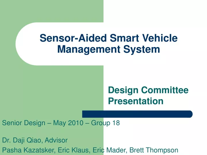
Sensor-Aided Smart Vehicle Management System. Design Committee Presentation. Senior Design – May 2010 – Group 18 Dr. Daji Qiao, Advisor Pasha Kazatsker, Eric Klaus, Eric Mader, Brett Thompson. Problem Statement. Residents of a gated community must act. Extra actions lead to apathy.

E N D
Sensor-Aided Smart Vehicle Management System Design Committee Presentation Senior Design – May 2010 – Group 18 Dr. Daji Qiao, Advisor Pasha Kazatsker, Eric Klaus, Eric Mader, Brett Thompson
Problem Statement • Residents of a gated community must act. • Extra actions lead to apathy. • Apathy leads to poor security. • Poor security on vehicles is undesirable!
General Solution • No added effort required. • Sensors provided for identification. • Users are paired with vehicles. • Only authorized pairs are allowed in or out.
Assumptions • Authorized users are in possession of a user sensor whenever attempting to operate a vehicle. • All entrances to the community implement a gate sensor. • Gate sensors shall be powered by a dedicated source, not a battery. • Emergency vehicles shall have the means to enter and exit the community. • Computers used to control the system shall have at least one operational USB port for each gate in the community.
System Limitations • Range of mesh sensors shall be in a maximum range of 60 meters of one another. • Vehicles shall have a location to conceal a vehicle sensor that is within 2 meters of the typical placement of a user sensor. • The user and vehicle sensors shall operate at reasonable levels of battery power consumption.
Requirements • System shall authenticate user and vehicle sensor pairs. • System shall send an alert if a vehicle is being stolen. • System shall command a gate to open for valid user and vehicle sensor pairs.
Engineering Principles • State diagrams • Critical Thinking • Product life cycle • Voltage/Current • Graph Theory • Wireless Communication
Design Tradeoffs • Battery Life vs. reliability/responsiveness • Security vs. accessibility • Security vs. code complexity • Ease of installation vs. elegance • Cost (us) vs. reliability • Cost (clients) vs. reliability
Platform • TelosB Motes • nesC/tinyOS • PHP • MySQL
Test Plan • PHASE 0: Component Testing • PHASE 1: Indoor System Testing • Using RC Car • Sensors/nodes mounted in test environment • PHASE 2: Outdoor System Testing • Using actual car • Sensors/nodes mounted in test area on campus