Download
1 / 40
400 likes | 410 Views
This chapter provides an introduction to the design approaches of wide area networks (WANs), focusing on circuit switching and packet switching. It explores the history and characteristics of switched communication networks, circuit switching networks, and the components of a public telephone network.

E N D
FIT1005 Wide Area Networks (WANs) Reference: Chapter 10 – Stallings 7E
Introduction • Approaches to wide area network design: • Circuit switching • Packet switching • Since the invention of the telephone: http://atcaonline.com/phone/ http://inventors.about.com/library/inventors/bltelephone.htm circuit switching has been the dominant technology for voice communications • Around 1970, development began on a new form of architecture for long-distance digital data communications known as packet switching
A Switched Communication Network • For transmission of data beyond a local area, communication is typically achieved by transmitting data from source to destination through a network of intermediate switching nodes • The (network) switching nodes are not concerned with the content of the data exchanged between workstations, their purpose is simply to move the data from source to destination
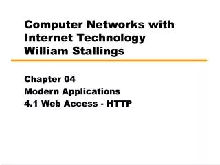
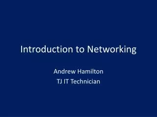
A Switched Communication Network General Characteristics • An interconnected collection of nodes • Nodes connected by transmission links • Data is transmitted from source to destination via a path made up of a connected series of links through the network • Nodes: • Dedicated - perform switching function only • Boundary (POP) - others also deliver/accept data to/from attached workstations • Always desirable to have more than one possible path between any two workstations to enhance reliability • Links: • Node to Node, shared via multiplexing (FDM, TDM, STDM) • Node to Workstation, dedicated (from point of view of network)
A Switched Communications Network B S S B B S S B B Workstation Network Switching Node
Circuit Switching Networks • There is a dedicated communication path between two stations: • That path is a connected sequence of links between switched network nodes • On each physical link, a logical channel (a subchannel allocated via FDM) is dedicated to a connection • Communication involves 3 phases: • Circuit establishment • Data transfer • Circuit disconnect
Circuit Switching Networks Circuit establishment • Before any signals can be transmitted, an end-to-end (station-to-station) circuit must be established Data transfer • Information can be transferred from the source to destination, once a connection is established • The data may be analog or digital, depending on the nature of the network • Generally the connection is full duplex Circuit disconnect • After some period of data transfer, the connection is terminated, usually by the action of one of the two stations • Signals must be propagated through the path to de-allocate resources
Circuit Switching Networks • The switches must have intelligence to make resource allocations and to devise a route through the network • Circuit switching can be rather inefficient: • Channel capacity is dedicated for the duration of a connection, even if no data are being transferred • For a voice connection, utilisation is higher • For a PC-to-Server connection, the capacity may be idle during most of the time of the connection
Circuit Switching Networks • In terms of performance, there is a delay prior to signal transfer for call establishment • However, once the circuit is established, the network is effectively transparent to the users • Information is transmitted at a fixed data rate with no delay other than the propagation delay through the transmission link • The delay at each switching node is negligible • Circuit switching was developed to handle voice traffic, but can also used for data traffic via use of a modem
Circuit Switching Networks • The best-known example of a circuit-switching network is the public telephone network • This is actually a collection of national networks interconnected to form the international service • Although originally designed and implemented to service analog telephone subscribers, gradually being converted to a digital network • Another well-known application of circuit switching is the private branch exchange (PBS), used to connect telephones within a building or office
Public Telephone Network A can be described using four generic architectural components: • Subscribers • The devices that attach to the network • It is still the case that most subscriber devices to public communications networks are telephones • But the percentage of data traffic increases year by year • Subscriber line • The link between the subscriber and the network, also referred to as the subscriber loop or local loop • Almost all local loop connections use twisted-pair wire • The length of a local loop is typically in a range up to tens of kilometres
Public Telephone Network • Exchanges • The switching centres in the network • A switching centre that directly supports subscribers is known as an end office • Typically, an end office will support many thousands of subscribers in a localised area • In addition, intermediate switching nodes are used • Trunks • The branches between exchanges • Trunks carry multiple voice frequency circuits using either FDM or TDM • Earlier these were referred to as carrier systems
Circuit Switching Concepts • A network built around a single circuit-switching node consists of a collection of stations attached to a central switching unit • The central switch establishes a dedicated path between any two devices that wish to communicate • The heart of a modern system is a digital switch • The function of the digital switch is to provide a transparent signal path between any pair of attached devices • The path is transparent in that it appears to the attached pair of devices that there is a direct connection between them
Circuit Switching Concepts • The network interface element represents the functions and hardware needed to connect digital devices, such as data processing devices and digital telephones, to the network • Analog telephones can also be attached if the network interface contains the logic for converting to digital signals • Trunks to other digital switches carry TDM signals and provide the links for constructing multiple-node networks
Circuit Switching Concepts The control unit performs 3 general tasks: • It establishes connections • This is generally done on demand, that is, at request of an attached device • To establish the connection, the control unit must handle and acknowledge the request, determine if the intended destination is free, and construct a a path through the switch • It must maintain the connection • Because the digital switch uses time division principles, this may require ongoing manipulation of the switching elements • However, the bits of communication are transferred transparently • It must tear down he connection, either in response to a request from one of the parties or for its own reasons
Circuit Switching Concepts Call Blocking • An important characteristic of a circuit-switching device is whether it is blocking or non blocking • Blocking occurs when the network is unable to connect two stations because all possible paths between them are already in use • A blocking network is one in which such blocking is possible • A non blocking network permits all stations to be connected (in pairs) at once and grant all possible connection requests as long as the called party is free • Voice traffic - When a network is supporting only voice traffic, a blocking configuration is generally acceptable, because it is expected that most phone calls are of short duration and that therefore only a fraction of the telephones will be engaged at any time
Circuit Switching Concepts Call Blocking Data traffic - when data processing devices are involved, these assumptions may be invalid • For example, for a data entry application, a terminal may be continuously connected to a computer for hours at a time • Hence, for a data applications, there is a requirement for a nonblocking or nearly nonblocking configuration
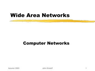
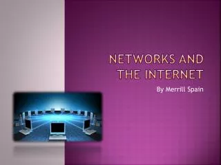
Circuit Switching Concepts Space Division Switching • One of the switching techniques internal to a single circuit switching nodes • It was originally developed for the analog environment and has been carried over into the digital realm • As the name implies, a space division switch is one which the signal paths are physically separate from one another • Each connection requires the establishment of a physical path through the switch that is dedicated solely to transfer of signals between the two end points • The basic building block of the switch is a metallic cross-point or semiconductor gate that can be enabled and disabled by a control unit
Fig 10.5 – Space Division Switch 10 X 10 = 100 cross points
Circuit Switching Concepts Space Division Switching The crossbar switch has a number of limitations: • The number of cross points grows with the square of the number of attached stations • This is costly for a large switch • The loss of a cross point prevents connection between the two devices whose lines intersect at that cross point • The cross points are inefficiently utilised • even when all of the attached devices are active, only a small fraction of the cross points are engaged
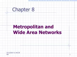
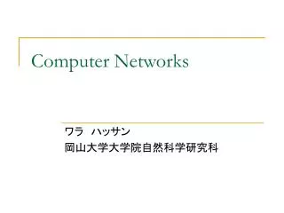
Circuit Switching Concepts Space Division Switching To overcome these limitations, multiple-stage switches are employed: • This type of arrangement has two advantages over a single-stage crossbar matrix • The number of cross points is reduced; in the example, the total number of cross points for 10 stations is reduced from 100 to 48 • There is more than one path through the network to connect two endpoints, increasing reliability • However, a multistage network requires a more complex control scheme • Another consideration with a multistage space division switch is that it may be blocking • A single-stage crossbar matrix is non blocking; that is a path is always available to connect an input to an output
Fig 10.6 – Three Stage Space Division Switch 5x2(10) + 5x2(10) + 2x2(4) + 2x2(4) + 5x2(10) + 5x2(10) = 48 cross points
Packet Switching Concepts • When circuit switching networks began to be used increasingly for data connections, two shortcomings became apparent: • In typical user/host data connection, much of the time the line is idle • Thus, with the data connections, a circuit-switching approach is inefficient • In a circuit-switching network, the connection provides for transmission at a fixed data rate • Thus, each of the two devices that are connected must transmit and receive at the same data rate as the other • This limits the utility of the network in interconnecting a variety of host computers and workstations
Packet Switching Concepts • In packet switching, data are transmitted in short packets • A typical upper bound on packet length is 1000 octets • If a source has a longer message to send, the message is broken up into a series of packets • Each packet contains a portion (or all for a short message) of the user’s data plus some control information • The control information, at a minimum, includes the information that the network requires to be able to route the packet through the network and deliver it to the intended destination
Packet Switching Concepts • At each node en route, a packet is received, stored briefly, and passed on to the next node • The packet-switching approach has a number of advantages over circuit-switching: • Line efficiency is greater, because a single node-to-node link can be dynamically (via TDM) shared by many packets over time • The packets are queued up and transmitted as rapidly as possible over the link • By contrast, with circuit switching, time on a node-to-node link is pre-allocated using TDM
Packet Switching Concepts • A packet-switching network can perform data-rate conversion • Two stations of different data rates can exchange packets because each connects to its node at its proper data rate • When traffic becomes heavy on a circuit-switching network, some calls are blocked • On a packet-switching network, packets are still accepted, but delivery delay increases • Priorities can be used • If a node has a number of packets queued for transmission, it can transmit the higher-priority packets first
Packet Switching Concepts • A network uses two approaches to handle a stream of packets as it attempts to route them through the network and deliver them to the intended destination: • Datagram Approach • Virtual Circuit Approach
Packet Switching Concepts Datagram Approach • Each packet is treated independently, with no reference to packets that have gone before • Each node chooses the next node on a packet’s path, taking into account information received from neighbouring nodes on traffic, line failures, and so on • So the packets, each with the same destination address, do not all follow the same route, and they may arrive out of sequence at the exit point: • It is up to the exit node or the destination to restore the packets to original order • Further, it is up to the exit node or destination to detect the loss of a packet and decide how to recover it
Packet Switching Concepts Virtual Circuit Approach • A pre-planned route is established before any packets are sent • Once the route is established, all the packets between a pair of communicating parties follow this same route through the network • Because the route is fixed for the duration of the logical connection, it is somewhat similar to a circuit in a circuit-switching network and is referred to as a virtual circuit • This does not mean that there is a dedicated path, as in circuit switching • A packet is still buffered at each node, and queued for out put over a line, while other packets on other virtual circuits may share the use of the line
Packet Switching Concepts Virtual Circuit Approach • Each packet contains a virtual circuit identifier as well as data • Each node on the pre-established route knows where to direct such packets; no routing decisions are required • At any time, each station can have more than one virtual circuit to any other station and can have virtual circuits to more than one station
Comparison of Circuit Switching and Packet Switching When a comparison of performance between the two types is done, we are concerned with 3 types of delay: • Propagation delay • The time it takes a signal to propagate from one node to the next • This time is generally negligible • Transmission time • The time it takes for a transmitter to send out a block of data • For example, it takes 1s to transmit a 10,000-bit block of data onto a 10-kbps line • Node delay • The time it takes for a node to perform necessary processing as it switches data
Comparison of Circuit Switching and Packet Switching • In circuit switching, once a connection is established, a constant data rate is provided to the connected stations • In the case of packet switching, a variable delay is introduced and packets arrive in a choppy manner • For packet switching, analog data must be converted to digital before transmission • Refer Table 10.2 Stallings 7E
Fig 10.15 – Event Timing for Circuit Switching and Packet Switching