Download
1 / 23
240 likes | 626 Views
Use of the Hardened Subminiature Telemetry and Sensor System (HSTSS) Technologies in NASA’s Space Shuttle Transportation System Upgrades. Robert E. Carpenter, PE HSTSS Systems Engineer U.S. Army STRICOM PM-ITTS/IMO Advanced Systems Technology, Inc. Peter T. Johnson

E N D
Use of the Hardened Subminiature Telemetry and Sensor System (HSTSS) Technologies in NASA’s Space Shuttle Transportation System Upgrades Robert E. Carpenter, PE HSTSS Systems Engineer U.S. Army STRICOM PM-ITTS/IMO Advanced Systems Technology, Inc. • Peter T. Johnson • Orbiter Instrumentation/Space Shuttle Upgrades • NASA/John F. Kennedy Space Center 1 P12
Shuttle Upgrade Program Needs: • Quickly instrument locations within NASA’s Space Shuttle that had never been considered to be areas of interest by the first generation Shuttle analysts. • Instrument aging Shuttle systems • Determine Sources of Unexplained Occurrences • Measure Aging Effects • Upgrade large obsolete electronics • Instrument Shuttle Upgrade Installations • Current Instrumentation System (Modular Auxiliary Data System (MADS) has limited capacity. • Add instrumentation to Get Away Specials and Hitchhiker Educational Experiments. 2 P12
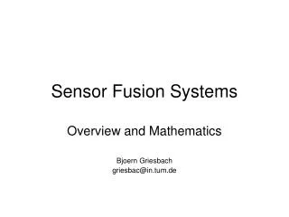
Need for Distributed System • The existing instrumentation system utilized on the Shuttle uses miles of copper wire to connect remote sensors to centrally located signal conditioning and digitizing hardware. The nature of HSTSS lends itself to distributed systems, wherein an area is instrumented, signal conditioned, and converted to a telemetry stream, which is then routed to a central location for archival or transmission over a single signal line. 3 P12
Orbiter Instrumentation Hardware Location • 1: FWD AVIONICS BAY 1 • DEDICATED SIG COND (1) • OI MDM • PCMMU No. 1 • PAYLOAD TAPE RECORDER • PDI • 3: FWD AVIONICS BAY 3A • DEDICATED SIG COND (1) • OI MDM (1) • 4: FWD AVIONICS BAY 3B • MASTER TIMING UNIT • 8: AFT AVIONICS BAY 5 • DEDICATED SIG COND (1) • OI MDM • W/B SIG COND (2) • 9: AFT AVIONICS BAY 6 • DEDICATED SIG COND (1) • OI MDM • 5: FWD RCS OI DSC (1) • 6. FLT DECK OI MDM • 7: AFT AVIONICS BAY 4 • DEDICATED SIG COND (1) • OI MDM • W/B SIG COND (4) • 2: FWD AVIONICS BAY 2 • DEDICATED SIG COND (1) • OI MDM (1) • PCMMU No. 2 • OPS TAPE RECORDER No. 1 • OPS TAPE RECORDER No. 2 10: OMS DSC (4) 11: FUEL CELL DSC (3) 4 P12
OPERATIONAL INSTRUMENTATION SUBSYSTEM BLOCK DIAGRAM { { } 128K Data & Clock NSP 2 Data & Clock PCM 2 S-Band XPNDR or Ku SIG PROC T-O Umb 128/192 kbps/Voice 64K T-O Umb Voice · 128 kbps 64 kbps 100 Hz NETWORK SIGNAL PROCESSOR 1 PCMMU 1 OPS 1 REC KU SIGNAL PROC · RF Link GPC 1 · 1.152 MHz Data P/L Port 0I Port T-O Umb · GPC 2 COMSEC Spacelab T-O Umb { 4.608 MHz PAYLOAD REC PSP1 Payload Data EIU (3) GPC Bus · PDI PSP2 GMT · GPC 3 OTB Time MTU · MET P/L 5 P/L Station Spacelab PTB 4.608 MHz COMSEC FM SIG PROC GPC 4 Data 1.152 MHz 100 Hz · P/L Port NETWORK SIGNAL PROCESSOR 2 FM SIG. PROC. RF Link PCMMU 2 OPS 2 REC 64 kbps 128 kbps · GPC 5 0I Port Voice · 128/192 kbps/Voice } { Data & Clock NSP 1 Data & Clock PCM 1 64K { T-O Umb S-Band XPNDR or Ku SIG PROC OI Data Bus 2 OI Data Bus 1 128K · · · · · · · · · MDM OF1 MDM OF2 MDM OF3 MDM OF4 MDM OA1 MDM OA2 MDM OA3 OF2 · SGSC TIRE PRESS SGSC TIRE PRESS SGSC TIRE PRESS SGSC TIRE PRESS WBSC (4 VMS OF2 WBSC (2 VMS OA01 OA03 DSC OM2 OM3 DSC OF2 DSC OF1 OF4 DSC OF3 DSC EDO1 DSC OM1 OM2 OM3 DSC OA1 OL1 DSC OA2 OR1 DSC OA3 OL2 OR2 DSC OM1 OM2 DSC OM2 0M3 DSC OM1 OM2 OM3 DSC OM1 OM2 OM3 DSC EDO2 1. SENSOR AND SUBSYSTEM INPUTS ARE ROUTED TO DSC’s AND MDM’s. 2.. ALL DSC’S EXCEPT OM3 HAVE MEASUREMENTS ROUTED TO C/W AND DISPLAY. 3. ALL DSC’S EXCEPT OM2, OM3, ED01, AND ED02 HAVE MEASUREMENTS ROUTED TO FLIGHT CRITICAL MDM’S. (FF OR FA MDM’S) 5 P12
Instrumentation “Toolkit” • Shuttle Instrumentation engineers need a “toolkit” of high performance, low mass, low power subminiature instrumentation hardware. • MEMS sensors • Systems on a Chip • Programmable Devices 6 P12
“Toolkit” Requirements • small size, weight, power requirements • simple installation • minimize mechanical, electrical impacts • distributed system • feed encoded signal to a central device for interleaving, processing, transmitting, or archival. • space certified (or at least space certifiable) • robust and easily configurable. • fit existing shuttle telemetry requirements and anticipated future telemetry needs. • be low cost • temporary or limited use installations The end goal is to determine the ability of the system described above to meet the needs of other, more critical systems. 7 P12
HSTSS Program Overview • Develop and demonstrate enabling technologies required to complete advanced instrumentation requirements of future Army, Navy, and Air Force munitions. • The HSTSS program is developing and high-g qualifying subminiature sensors and instrumentation parts and packages to invoke a high volume, low cost production path suitable for COTS processes required in current military development and re-capitalization efforts. • HSTSS goals are accomplished by combining capabilities of the armed services and industry, invoking the processes of effective Integrated Product Teams and partnering agreements. • As smart weapons (munitions and missiles) become increasingly complex, it is necessary to obtain sufficient critical data throughout a munition life cycle to successfully complete development, diagnostic, training and tactical applications. Projectile aerodynamic characterization, evaluation of guidance and maneuver systems, and measures-of-truth for Inertial Measurement Units (IMU) are examples of needed measurement capabilities. 8 P12
Fig. 2: Complete Telemetry system, installed in The tracer well of a kinetic energy penetrator rod Digital Data Antenna Sensor Signal Conditioningand Multiplexing PCM Encoder FM Transmitter Sensor Sensor Power supply (battery) Fig 1: Block Diagram of a typical PCM/FM Telemetry System HSTSS Characteristics • HSTSS technologies include sensors, data acquisition chipsets (signal conditioning, multiplexing, and encoding), telemetry transmitters, antennae, high-g/high-density electronics packaging technologies, and power sources. • HSTSS technologies are available in modules, packaged IC’s, and bare die. • HSTSS technologies must survive and operate in the harsh environments that weapon systems experience during launch, flight, and impact. HSTSS supported direct fire munitions testing (figure 2), volume of one cubic inch, accelerations of over 65,000 g’s. 9 P12
Shuttle/HSTSS Project Description (Initial Experiment) The initial collaborative project between NASA and the HSTSS program is intended to verify the viability of HSTSS applicability and efficacy. To accomplish this, a 19-channel PCM instrumentation system comprising an encoder, signal conditioning and multiplexing will be utilized. Sensor inputs will include a combination of existing Orbiter devices and HSTSS or COTS MEMS accelerometers, temperature, and pressure sensors. The HSTSS devices will be packaged in a suitable mounting for installation inside the wing, aft, or payload bay of the Space Shuttle, with other locations to be determined. This system will comprise a programmable “system on a chip” with sensor and digital data inputs. System power (5 volts) will be derived from the Shuttle 28 Vdc power system. Output will be a PCM stream that will either be recorded on-board, mixed into shuttle telemetry, or transmitted to a local receiver. The system will operate over several or all flight phases on multiple missions to accurately gauge the reliability of the system. Cross correlation of the resulting data with existing Orbiter instrumentation will further validate the results. This project is intended to fly in the mid ’02 timeframe in location that is presently under assessment. Part of the demonstration is to implement the entire system within an unreasonably short timeframe (6 to 15 months from recognition of need (perceived or real)) to flight. 10 P12
Potential Proof of Concept Implementations • Mobile Launch Platform (MLP) - Environment assessment for future implementation of high speed network interface electronic equipment installation. • Orbiter Payload Bay • Environmental measurements beyond standard services that the Orbiter presently provides. • Unanticipated structural responses relating to ISS activities. • Provide a toolkit to educators flying low cost Hitchhiker and Get Away Special (GSA) experiments. • Orbiter Aft • Many need upgrades going into the Orbiter aft: • Advanced Health Management System (AHMS) • Electric Auxiliary Power Unit (EAPU) • Provide a means to quickly acquire environmental assessment of an installation package - either before or after installation. 11 P12
KSC Orbiter Upgrades Commitment • Agreement from the KSC Spaceport Engineering and Technology Office to support an HSTSS based experiment in conjunction with Program Manager Instrumentation Targets and Threats Simulators – Instrumentation Management Office, U.S. Army STRICOM. • Fly in the mid ’02 timeframe in location that is presently under assessment. Part of the demonstration is to implement the entire system (less the BRSS Paperwork documentation process) within an unreasonably short timeframe (6 to 15 months from recognition of need (perceived or real) to flight. 12 P12
Chip-On-Board FPGA Encoder 13 P12
4 analog channels expandable to 128 using the SCIC-DVC-101 12 bit A/D converter (480 KSPS) User configurable including sub-commutation and super commutation 3 Digital Configurable Ports (16-bit inputs) Serial Input Port (115K baud) PCM NRZ-L or RNRZ-L (IRIG-106) output Selectable internal/external clock Provides time delay with external memory Single 5 Volt Operation 176 Lead Thin Quad Flatpack Available In Die Form Developed for HSTSS by Systems & Processes Engineering Corporation, Austin, TX. Programmable PCM ASIC 14 P12
16 Analog Inputs User Configurable Programmable Gain and Offset Programmable 4 or 8 pole filtering Over Voltage Protection Five (5) Volt Operation, 11mA per channel used (worst case app. 900mW w/16channels) Available in TQFP or in die Form The Input Signal Conditioner (ISC) ASIC provides 16 analog input channels that can be independently amplified, offset, and filtered. The 16 channels are then multiplexed into one analog channel for output. The channel gain, offset, and filtering bandwidth are channel independent and digitally controlled through a configuration interface. Developed by SPEC for HSTSS. Input Signal Conditioner (ISC) ASIC 15 P12
Programmable Time Delay Loop Operating Mode Up To 3 Analog Inputs Optional Playback at Reduced Rates 175ms Maximum Delay With External Memory 5 Volt Operation Available in TQFP or in die Form The Delay/Repeater provides three channels of delayed or delayed and repeated analog signals with a bandwidth range of 0 to 60 kHz. The DAC Delay/Repeater provides up to 20 ms of time delay in 5 ms increments on-chip. Delay of up to 175 ms can be supported using an external COTS SRAM. The digitized outputs of the A/D converters (12 bits at 150 KSPS) are bussed and written to internal memory (3 channels x 12 bits x 150 KSPS x 0.02 sec = 108 Kbits) or external memory interface (256K x 8 bits SRAM). After the data is read from memory, it is fed into three independent digital-to-analog (D/A) converters for signal reconstruction. Output filters remove spurs generated by the D/A converter. Developed by SPEC for HSTSS. Delay/Repeater (DR) ASIC 16 P12
TQFP Package – cut-away view SPEC Delay/Repeater (Packaged TQFP and Die) Packaging of DAC ASIC’s 17 P12
MEMS accelerometers and rate sensors developed for automotive and consumer electronics industries have been under evaluation by the HSTSS program for use in high shock military applications. These very inexpensive COTS products are extremely rugged and perform admirably, far exceeding their original industrial requirements. HSTSS uses include measurement of body-fixed axial/radial accelerations, drag, thrust, etc. for use in in-flight aerodynamic characterization and in-bore environment characterization, muzzle exit vibration, muzzle velocity determination. MEMS Devices Analog Devices ARS-60 Rate Grade Sensor Package (0.35 inch foot print) Analog Devices ADXL series accelerometers, shock qualified to 30 Kg’s. Single and multi axis. HSTSS Accelerometer Flight Data gathered in-bore during launch. 18 P12
Pressure Transducer Processed PZT wafer The objective of the HSTSS pressure sensor development efforts is to design, fabricate, and test a high-g PZT MEMS pressure sensor for the Test and Evaluation community so that a rugged flight worthy instrument can aid in the test and evaluation of the current and developmental weaponry. Such a system will provide miniaturized, high-g survivable pressure sensors that could be used in a variety of harsh environments. This project is executed through a partnership between HSTSS, ARL-WMRD, JHU-APL, ATC (DARPA Funded Program). It is suggested that this type of non-ported pressure sensor may be useful for instrumenting Space Shuttle Orbiter external surfaces. 19 P12
HSTSS Transmitter 20 P12
Stacked Die mounted on MCM High Density Packaging • Objectives: • Evaluate microelectronics assembly techniques for ballistic environment • Establish boundaries • Adopt & modify commercial techniques • Evaluate substrate technologies • Evaluate interconnection schemes between substrates • Explore advanced packaging techniques • Conduct demonstrations using HSTSS products • HSTSS Partners • John Hopkins Applied Physics Laboratory (APL) • Microelectronics & Computer Technology Corp. (MCC) Flight proven TM electronics packaged on reprogrammable MCM Stacked Interconnected MCM’s 21 P12
HSTSS developed battery technology is physically conformable and will support launch accelerations of 100,000 g’s. To accomplish this, HSTSS contracts with multiple battery vendors have modified COTS technologies for harsh environments. Rechargeable Lithium-Ion technology is: composed of solid electrolyte, environmentally friendly, customizable for various applications high in energy density (125 Wh/Kg), conformal foil laminate packaging, provides excellent cyclability. Li/MnO2 Pouch Technology provides high energy density (250 Wh/Kg), conformal foil laminate packaging, - 20 C to +70 C operation, rapid prototyping, is customizable for various applications, high rate capability, design flexibility. Conformal Lithium Batteries Encapsulated Artillery Nose Fuze Battery 22 P12
Issues & Concerns • Radiation requirements • Although HSTSS is acceleration hardened, single event upsets related to radiation is a Programmatic issue. • Potential part of the demonstration • Data recording • Method is TBD • Data format • HSTSS components output NRZ-L • Proposed Upgraded Auxiliary Instrumentation System will only accept Bi- L PCM data. 23 P12