Download
1 / 60
600 likes | 767 Views
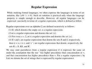
Regular Expression Manipulation FSM Model. Sequential Machine Theory Prof. K. J. Hintz Department of Electrical and Computer Engineering Lecture 6. Modifications by Marek Perkowski. Null Machine. 3 Methods for Proving That a Machine Accepts No Words By inspection

E N D
Regular Expression ManipulationFSM Model Sequential Machine Theory Prof. K. J. Hintz Department of Electrical and Computer Engineering Lecture 6 Modifications by Marek Perkowski
Null Machine 3 Methods for Proving That a Machine Accepts No Words • By inspection • Any path from the start state to a final state means that at least one word is accepted by the machine • By state diagram manipulation • If a final state is relabeled as a start state, then the machine must accept at least one word
Null Machine • By converting the regular expression into a deterministic FA • If possible, FA must accept at least one word • Conversion to FA may not be possible • Machine may have no final states. • There is no path from the initial state to any final state.
State Diagram Manipulation A procedure to determine if a machine accepts no strings • Remove all edges (arrows) to the start state. • From the start state, identify all single-step “next states.” • Relabel these “next states” as start states and eliminate the edges used to get there. • go to (b) • If a final state is relabeled as a start state, then the machine must accept at least one word.
State Diagram Manipulation Does Not Accept Any Word Since There Is No Path From - To +.
The Complement Machine • A Complement Machine Accepts All ExpressionsOther Than Those Accepted by the Original Machine • Method • Change all non-final states into final states • Change all final states into non-final states • Leave start state unchanged
Language Decidability Methods for Determining If Two Regular Expressions Define the Same Language • Language Enumeration with 1:1 correspondence between the 2 languages. • The regular languages can be accepted by identical FAs. • Generate
Language Overlap • If the Overlap Language Is NOT the Null Set, Then There Is Some Word in L1 Which Is Not Accepted by L2 and Vice Versa. • If the Overlap Language Accepts the Null String, Then the Languages Are Not Equal.
DeMorgan’s Theorem Applies Equally Well to Sets As Well As Boolean Algebra
Regular Expression Equivalence Methodology • Construct the complement machines • Apply DeMorgan’s theorem since it is difficult to form the intersect machine
Regular Expression Equivalence Take the Unions of the Complemented and Non-complementedSeveral Times to Determine Whether Loverlap Is the Null Set or Not
RE Equivalence Example* Two REs are represented by their equivalent FAs (FA1 does = FA2) *Cohen, Prob. 2, page 233.
RE Equivalence Example Form the Complement Machines
RE Equivalence Example Make the Product Machine of FA2 and the Complement of FA1.
RE Equivalence Example • States of Product Machine, FA1-bar & FA2 • Only One Start State / Multiple Final States
State Diagram of Product FA1-Bar, FA2
Reduced State Diagram Non-Reachable States Removed
RE Equivalence Example • Take the Complement Of the Union by changing final states to non-final and vice-versa • No Final States, So Complement FA Accepts No Words
RE Equivalence Example Do the Same for the Right Term of Loverlap
RE Equivalence Example • Application of Same Procedure to Preceding Machine Also Results in No Recognizable Words. • Since Both Terms of Loverlap are Null, Then REs Are Equivalent Since Their Union Is Null.
Moore & Mealy Machines • The Behavior of Sequential Machines Depends on Previous Inputs. • Moore Machine • Output only depends on present state • Mealy Machine • Output depends on both the present state and the present input
Moore & Mealy Machines Equivalent Descriptive Methods • Transition (state) table • Transition (state) diagram • Operational descriptions using set theory • (Language recognized by the machine)
Comb Ckt Comb Ckt Memory Moore Machine Input Present State Output Output Is Only a Function of Present State
input on state/ output A/0 B/1 off off Legend C/0 D/0 etc. Primitive State Diagram, Moore
x1x0 10 s1s0/z 00/1 01/0 00 01 Legend 10/1 11/1 etc. Moore Machine State Diagram
Comb Ckt Comb Ckt Memory Mealy Machine Input Present State Output Output Is Function of Present State AND Present Input
input/output on/0 state A B off/1 off /0 Legend C D etc. Primitive State Diagram, Mealy
x1x0 /z 10 /0 s1s0 00 01 00 /1 01 /1 Legend 10 11 etc. Mealy Machine State Diagram
FSM Design Approaches • “One-Hot” • One flip-flop is used to represent each state • Costly in terms of discrete hardware, but trivial to design • Efficient in FPGAs because FF part of each CLB • Binary Coded State • n flip-flops used to store 2nstates • Most efficient • Need to account for unused states
FSM and Clocks • Synchronous FSMs may change state only when a unique input, the clock, occurs • Asynchronous FSMs may change state when input changes • Next state depends on present input and present state for both Moore and Mealy
Synchronous versus Asynchronous Machines in Design • Synchronous FSMs • Easier to design, turn the crank • Slower operation • Asynchronous • Harder to design because of potential for races, iterative solutions • Faster operation
Mealy “0101” Detector M = ( S, I, O, d, b ) S: { A, B, C, D } I: { ‘0’, ‘1’ } O: { 0, 1 } = { not detected, detected} d: next slide b: next slide
Mealy Transition/Output Table Next State/Output
A B C D “0101“ State Diagram ‘1’/0 ‘0’/0 ‘0’/0 ‘1’/0 ‘0’/0 ‘1’/0 ‘1’/1 ‘0’/0
Moore “0101” Detector M = ( S, I, O, d, l ) S: { A, B, C, D, E } I: { ‘0’, ‘1’ } O: { 0, 1 } = { not detected, detected} d: next slide l: next slide
Moore Transition/Output Table Next State
D/0 E/1 Moore “0101“ State Diagram ‘0’ ‘1’ ‘0’ detected ‘0’ A/0 B/0 ‘0’ ‘1’ ‘1’ ‘1’ ‘0’ C/0 ‘0’ ‘1’ “01” det “0101” det “010” det
Asynchronous FSM Fundamental Mode Assumption • Only one inputcan change at a time • Analysis too complicated if multiple inputs are allowed to change simultaneously • Circuit must be allowed to settle to its final value before an input is allowed to change • Behavior is unpredictable (nondeterministic) if circuit not allowed to settle
Asynch. Design Difficulties Delay in Feedback Path • Not reproducible from implementation to implementation • Variable • may be temperature or electrical parameter dependent within the same device • Analog • not known exactly
Stable State • PS = present state • NS = next state • PS = NS = Stability • Machine may pass through none or more intermediate states on the way to a stable state • Desired behavior since only time delay separates PS from NS • Oscillation • Machine never stabilizes in a single state
Races • A Race Occurs in a Transition From One State to the Next When More Than One Next State Variables Changes in Response to a Change in an Input • Slight Environment Differences Can Cause Different State Transitions to Occur • Supply voltage • Temperature, etc.
PS 01 11 00 if Y1 changes first if Y2 changes first 10 desired NS Races
Types of Races • Non-Critical • Machine stabilizes in desired state, but may transition through other states on the way • Critical • Machine does not stabilize in the desired state
01 11 00 10 00 critical race Races PS if Y2 changes first if Y1 changes first desired NS non- critical race
Asynchronous FSM Benefits • Fastest FSM • Economical • No need for clock generator • Output Changes When Signals Change, Not When Clock Occurs • Data Can Be Passed Between Two Circuits Which Are Not Synchronized • In some technologies, like quantum, clock is just not possible to exist