Download
1 / 28
380 likes | 987 Views
Paranasal Sinuses Imaging. Prof. J. Stelmark. PARANASAL SINUSES

E N D
Paranasal Sinuses Imaging Prof. J. Stelmark
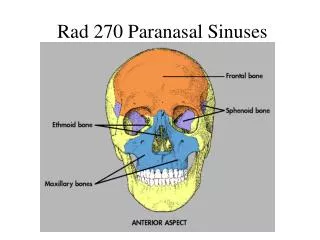
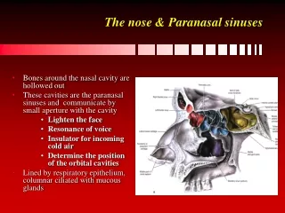
PARANASAL SINUSES • The large, air-filled cavities of the paranasal sinuses are sometimes called the accessory nasal sinuses because they are lined with mucous membrane, which is continuous with the nasal cavity. These sinuses are divided into four groups, according to the bones that contain them: • Maxillary (2) Maxillary (facial) bones • 2. Frontal (usually 2) Frontal (cranial) bones • 3. Ethmoid (many) Ethmoid (cranial) bones • 4. Sphenoid (cranial) bone
Only the maxillary sinuses are part of the facial bone structure. The frontal, ethmoid, and sphenoid sinuses are contained within their respective cranial bones. The paranasal sinuses begin to develop in the fetus, but only the maxillary sinuses exhibit a definite cavity at birth. The frontal and sphenoid sinuses begin to be visible on radiographs at age 6 or 7. The ethmoid sinuses develop last. All the paranasal sinuses generally are fully developed by the late teenage years.
Maxillary Sinuses The large maxillary sinuses are paired structures, one of which is located within the body of each maxillary bone. An older term for maxillary sinus is antrum, an abbreviation for Antrum of Highmore. Each maxillary sinus is shaped somewhat like a pyramid on a frontal view. Laterally, they appear more cubic. The average total vertical dimension is between 3 and 4 cm, and the other dimensions are between 2.5 and 3 cm.
Frontal Sinuses The frontal sinuses are located between the inner and outer tables of the skull, posterior to the glabella; they rarely become aerated before age 6. The maxillary sinuses are always paired and are usually fairly symmetric in size and shape; the frontal sinuses are rarely symmetric. The frontal sinuses usually are separated by a septum, which deviates from one side to the other or may be absent entirely, resulting in a single cavity.
Ethmoid Sinuses The ethmoid sinuses are contained within the lateral masses or labyrinths of the ethmoid bone. These air cells are grouped into anterior, middle, and posterior collections, but they all intercommunicate. When viewed from the side, the anterior ethmoid sinuses appear to fill the orbits. This occurs because portions of the ethmoid sinuses are contained in the lateral masses of the ethmoid bone, which helps to form the medial wall of each orbit.
Sphenoid Sinuses The sphenoid sinuses lie in the body of the sphenoid bone directly below the sella turcica. The body of the sphenoid that contains these sinuses is cubic and frequently is divided by a thin septum to form two cavities. This septum may be incomplete or absent entirely, however, resulting in only one cavity.
PARANASAL SINUSES Technical Factors A medium kV range of 70 to 80 is commonly used to provide sufficient contrast of the air-filled paranasal sinuses. Optimum density as controlled by the mAs is especially important for sinus radiography to visualize pathology within the sinus cavities. A small focal spot should be used for maximum detail. As with cranial and facial bone imaging, gonadal shielding is not useful in reducing gonadal exposure, but shields over the pelvic area may be used for patient reassurance. Close collimation and elimination of unnecessary repeats are the best measures for reducing radiation dose in sinus and temporal bone radiography.
LATERAL POSITION—RIGHT OR LEFT LATERAL: SINUSES Pathology Demonstrated Inflammatory conditions and sinus polyps or cysts. Technical Factors Moving or stationary grid • 65 to 75 kV range • Small focal spot
Part Position • Place lateral aspect of head against table/upright Bucky surface, with side of interest closest to IR. • Adjust head into a true lateral position, moving body in an oblique direction as needed for patient's comfort (midsagittal plane parallel to IR). • Align IPL perpendicular to IR (ensures no tilt). • Adjust chin to align IOML perpendicular to front edge of IR.
Central Ray • Align a horizontal CR perpendicular to the IR. • Center CR to a point midway between outer canthus and EAM. • Center IR to CR. • Minimum SID is 40 inches (100 cm).
Respiration Suspend respiration during exposure. Notes: To visualize air-fluid levels, an erect position with a horizontal beam is required. Fluid within the paranasal sinus cavities is thick and gelatin-like, causing it to cling to the cavity walls. To visualize this fluid, allow a short time (at least 5 minutes) for the fluid to settle after a patient's position has been changed (i.e., from recumbent to erect). If patient is unable to be placed in the upright position, the image may be obtained with the use of a horizontal beam.
Structures Shown: • All four paranasal sinus groups are shown.
PA PROJECTION: SINUSES Caldwell Method Pathology Demonstrated Inflammatory conditions and sinus polyps/cysts are shown.
Part Position • Place patient's nose and forehead against upright Bucky or table with neck extended to elevate the OML 15° from horizontal. A radiolucent support between forehead and upright Bucky or table may be used to maintain this position. CR remains horizontal. (alternate method if Bucky can be tilted 15°.) • Align MSP perpendicular to midline of grid or upright Bucky surface. • Center IR to CR and to nasion, ensuring no rotation.
Central Ray • Align CR horizontal, parallel with the floor. • Center CR to exit at nasion. • Minimum SID is 40 inches (100 cm).
Structures Shown: • Frontal sinuses projected above the frontonasal suture. • Anterior ethmoid air cells visualized lateral to each nasal bone, directly below the frontal sinuses.
PARIETOACANTHIAL PROJECTION: SINUSES Waters Method Pathology Demonstrated Inflammatory conditions and sinus polyps are shown.
Part Position • Extend neck, placing chin and nose against table/upright Bucky surface. • Adjust head until MML is perpendicular to IR; OML will form a 37° angle with the plane of the IR. • Position the MSP perpendicular to the midline of grid or table/upright Bucky surface. • Ensure that no rotation or tilt exists. • Center IR to CR and to acanthion.
Central Ray • Align a horizontal CR perpendicular to the IR centered to exit at the acanthion. • Minimum SID is 40 inches (100 cm).
Structures Shown: • Maxillary sinuses with the inferior aspect visualized free from superimposing alveolar processes and petrous ridges, the inferior orbital rim, and an oblique view of the frontal sinuses
SUBMENTOVERTEX (SMV) PROJECTION: SINUSES Pathology Demonstrated Inflammatory conditions (sinusitis, secondary osteomyelitis) and sinus polyps are shown.
Part Position • Raise chin, hyperextend neck if possible until IOML is parallel to table/upright Bucky surface. • Head rests on vertex of skull. • Align MSP perpendicular to midline of the grid or table/upright Bucky surface; ensure no rotation or tilt.
Central Ray • CR directed perpendicular to IOML • CR centered midway between angles of mandible, at a level 1½ to 2 inches (4 to 5 cm) inferior to mandibular symphysis • CR centered to IR • Minimum SID of 40 inches (100 cm)
Structures Shown: • Sphenoid sinuses, ethmoid sinuses, nasal fossae, and maxillary sinuses.
PARIETOACANTHIAL TRANSORAL PROJECTION: SINUSES Open Mouth Waters Method
Structures Shown: • Maxillary sinuses with the inferior aspect visualized, free from superimposing alveolar processes and petrous ridges, the inferior orbital rim, an oblique view of the frontal sinuses, and the sphenoid sinuses visualized through the open mouth.